Arduino_C Tutorial
1. About Arduino IDE
1.1. Install Arduino IDE(Important)
Arduino IDE provides all the software needed to complete Arduino projects, which allows us to write programs and upload them to the Arduino board.
Arduino IDE 2.3.3 is published as an open source tool and is improved based on Arduino IDE 1.x. It comes with improved user interfaces, boards and library managers, debuggers, auto-complete capabilities, etc.
In this tutorial, we will demonstrate how to download and install Arduino IDE 2.3.3 on a Windows, MacOS, or Linux computer.
⚠️ATTENTION: In this tutorial, we use Arduino IDE 2.3.3. Other versions may not be compatible.
Requirement
Windows - Win 10 or later versions, 64 bit
Linux - 64 bit
MacOS - 64 bit
Download
1. access Arduino IDE 2.3.3
2. download the IDE version that is compatible with your computer.

⚠️NOTE: Arduino IDE version updates fast and advanced versions may fail to compile codes. Therefore, we provide the Arduino IDE 2.3.3 package.
Installation
Windows
1. Click arduino-ide_xxxx.exe file to execute the file.
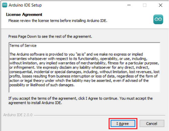
2. Read license agreement and click “I Agree”.
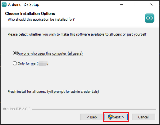
3. Tick “Anyone who uses this conputer(all users)”, and “Next”.
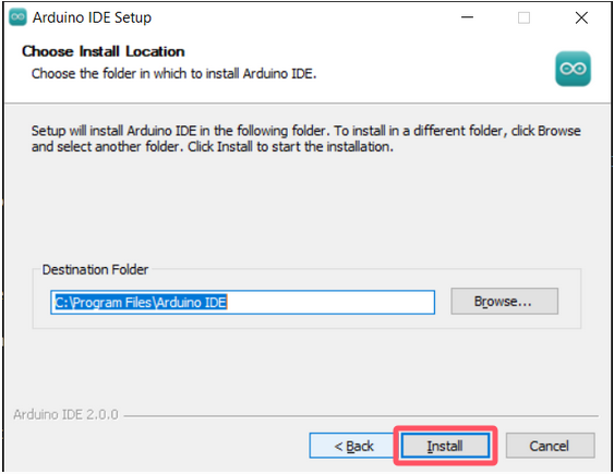
4. Choose an installation path and click “Install”.
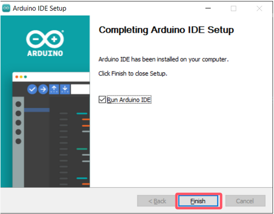
5. “Finish”.
MacOS:
Download arduino_ide_xxxx.dmg , and copy Arduino IDE.app to Applications file to install the Arduino IDE.

Linux:
For how to install Arduino IDE 2.3.3 on Linux, please refer to: https://docs.arduino.cc/software/ide-v2/tutorials/getting-started/ide-v2-downloading-and-installing/#linux
Enablement
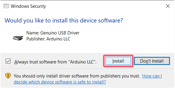
1. Open Arduino IDE 2.3.3 and it will install Arduino AVR board and built-in libraries automatically.

2. The firewall or Security Centres may pop up some windows asking if you want to install drivers. Please install.
3. Now the Arduino IDE is ready!
⚠️ATTENTION: If some installations don’t work due to issues like poor network, re-open Arduino IDE to complete the rest of the installation. After that, “Output” does not open automatically unless you click “Verify” or “Upload”.
1.2. Install Driver(Important)
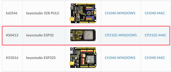
A driver is required to enable the ESP32 main board. Otherwise, there will be no COM port to be connected on the computer.
How to install driver: https://docs.keyestudio.com/projects/Arduino/en/latest/Arduino%20IDE%20Tutorial.html#install-driver
Enter the corresponding guide according to ESP32 board and operating system.
1.3. Arduino IDE Toolbar

1. Verify - compiles your code to your Arduino Board.
2. Verify / Upload - compiles and uploads your code to your Arduino Board. The on-board RX and TX LED quickly flash until uploading finishes.
3. Debugger - test and debug programs in real time.
4. Select Board - choose board and port.
5. Serial Plotter - displays serial data in a method of line graph
6. Serial Monitor - opens the Serial Monitor tool, as a new tab in the console.
7. File - includes new Sketch, open Sketch, open recently used code, open sample code, close the IDE, save code, preferences, advanced Settings, etc.
8. Edit - includes copy, paste, automatic formatting, font size, etc. (shortcut keys are recommended).
9. Sketch - includes verify\compile, upload code, import library and so on.
10. Tools - The most important two are development board and port. They must be set before uploading code.
11. Help - Views the IDE version and official reference documents.
12. Output Bar - alter output.
13. IDE prompt area -Uploading fails or succeeds & Serial monitor display area.
14. Board & Port - preview board model and port. You may re-set in “Tools → Board / Port”.
15. Code editing area
16. Sketchbook - here you will find all of your sketches locally stored on your computer.
17. Boards Manager - install or remove Arduino Boards.
18. Library Manager - browse through thousands of Arduino libraries or import local libraries.
19. Debugger - test and debug programs in real time.
20. Search - search for keywords in your code.
1.4. Install ESP32 Board(Important)
ESP32 board needs to be installed in Arduino IDE before using.
Install ESP32
1. Click “File → Preferences”.
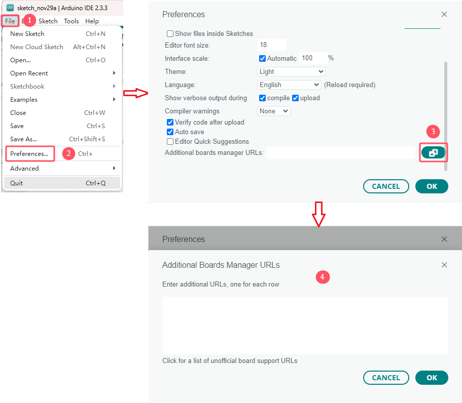
2. Copy and paste the link:https://espressif.github.io/arduino-esp32/package_esp32_index.json into Additional boards manager URLs and click OK.
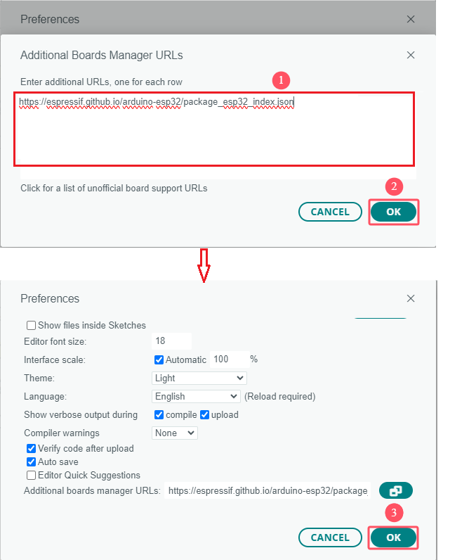
3. Select the icon of board manager to search for “ESP32” and click version 3.1.3 to “Install”. (⚠️Note that here we adopt 3.1.3 version of the ESP32. Installation may fail if you choose another versions.)
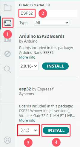
3. Now the ESP32 is installed.
Upload Code
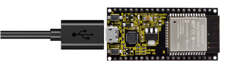
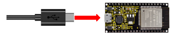
1. Connect ESP32 WROOM 32 to your computer via Micro USB cable.
2. Click “Tools” → “Board” → “esp32” to choose ESP32 Dev Module.

3. After connecting, click “Tools” → “Port”.

4. For ESP32, you need to click “Select other board and port” to set them manually.
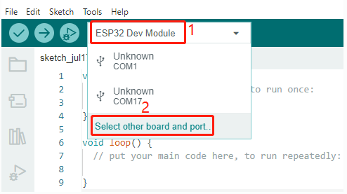
5. Search “ESP32 Dev Module” and click “OK”.

6. After that, you can choose them easily. Yet, at next time, ESP32 may be not accessed in it, so just set them again.

7. Now its ready for uploading code to ESP32.
1.5. Import Arduino Library(Important)
Libraries are a collection of pre-written code or functions that extend the functionality of the Arduino IDE, so that they allow you to save time and effort to code complex functions.
⚠️ATTENTION: Please import the libraries we provided! Manual import is recommended!
Method One: Manual Import
Except for Arduino library manager, you may import your own library manually.
1. Click Sketch → Include Library → Add .ZIP Library….

2. Locate in …\ Library \ Arduino_Library file and choose library zips to “Open”.
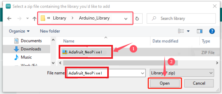
3. After that, you will see “Library installed”. You can use this library directly next time you need it.
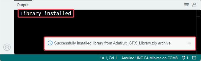
4. Import the rest libraries as well.
Method Two: Library Manager
There are many libraries are included in “Arduino Library Manager”.
1. In Library Manager, search for the desired library by name or browse different categories.
⚠️ATTENTION: Prompts are written in projects that require libraries. For example, “Herein, Adafruit_NeoPixel library is included. Please install it in Library Manager.”
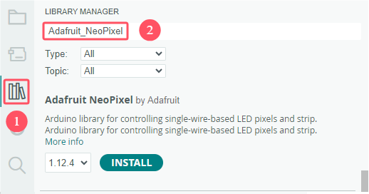
2. Find the library and Install. If “INSTALL WITHOUT DEPENDENCIES” and “INSTALL ALL” appears, choose “INSTALL ALL”. So do the other libraries.

3. Arduino IDE downloads the library automatically.

4. Other libraries are the same.
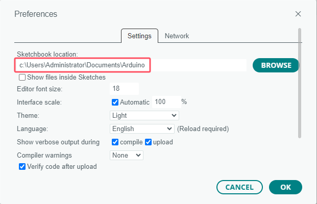
Path to Library
If you installed the library using the above method, it is in the default library directory of the Arduino IDE: C:\Users\xxx\Documents\Arduino\libraries.
If not, enter “File” → “Preferences” to check the path.

For details, please visit: Installing libraries in Arduino IDE 2
2. Projects:
Project 01: 6812 RGB
1. Description:
There are 4 RGB LEDs can be widely used in the decoration of buildings, bridges, roads, gardens, courtyards and so on by colors adjustment.
In this experiment, we will demonstrate different lighting effects with them.
2. Knowledge:
Working Principle
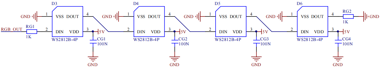
From the schematic diagram, we can see that these four pixel lighting beads are all connected in series. In fact, no matter how many they are, we can use a pin to control a light and let it display any color. The pixel point contains a data latch signal shaping amplifier drive circuit, a high-precision internal oscillator and a 12V high-voltage programmable constant current control part, which effectively ensures the color of the pixel point light is highly consistent.
The data protocol adopts a single-wire zero-code communication method. After the pixel is powered up and reset, the S terminal receives the data transmitted from the controller. The first 24bit data sent is extracted by the first pixel and sent to the data latch of the pixel.
3. Test Code:
The SK6812RGB on the PCB board is controlled by the GPIO 14 of the ESP32 board
/*
  Project 01 SK6812 RGB
  4 RGBs for various lighting effects.
*/
#include <Adafruit_NeoPixel.h>

#define PIN  14

// Parameter 1 = number of pixels in strip
// Parameter 2 = Arduino pin number (most are valid)
// Parameter 3 = pixel type flags, add together as needed:
//   NEO_KHZ800  800 KHz bitstream (most NeoPixel products w/WS2812 LEDs)
//   NEO_KHZ400  400 KHz (classic 'v1' (not v2) FLORA pixels, WS2811 drivers)
//   NEO_GRB     Pixels are wired for GRB bitstream (most NeoPixel products)
//   NEO_RGB     Pixels are wired for RGB bitstream (v1 FLORA pixels, not v2)
Adafruit_NeoPixel strip = Adafruit_NeoPixel(60, PIN, NEO_GRB + NEO_KHZ800);

// IMPORTANT: To reduce NeoPixel burnout risk, add 1000 uF capacitor across pixel power leads, add 300 - 500 Ohm resistor on first pixel's data input and minimize distance between Arduino and first pixel. Avoid connecting on a live circuit...if you must, connect GND first.

void setup() {
  strip.begin();
  strip.show(); // Initialize all pixels to 'off'
}

void loop() {
  // Some example procedures showing how to display to the pixels:
  colorWipe(strip.Color(255, 0, 0), 50); // Red
  colorWipe(strip.Color(0, 255, 0), 50); // Green
  colorWipe(strip.Color(0, 0, 255), 50); // Blue
  // Send a theater pixel chase in...
  theaterChase(strip.Color(127, 127, 127), 50); // White
  theaterChase(strip.Color(127,   0,   0), 50); // Red
  theaterChase(strip.Color(  0,   0, 127), 50); // Blue

  rainbow(20);
  rainbowCycle(20);
  theaterChaseRainbow(50);
}

// Fill the dots one after the other with a color
void colorWipe(uint32_t c, uint8_t wait) {
  for(uint16_t i=0; i<strip.numPixels(); i++) {
      strip.setPixelColor(i, c);
      strip.show();
      delay(wait);
  }
}

void rainbow(uint8_t wait) {
  uint16_t i, j;

  for(j=0; j<256; j++) {
    for(i=0; i<strip.numPixels(); i++) {
      strip.setPixelColor(i, Wheel((i+j) & 255));
    }
    strip.show();
    delay(wait);
  }
}

// Slightly different, this makes the rainbow equally distributed throughout
void rainbowCycle(uint8_t wait) {
  uint16_t i, j;

  for(j=0; j<256*5; j++) { // 5 cycles of all colors on wheel
    for(i=0; i< strip.numPixels(); i++) {
      strip.setPixelColor(i, Wheel(((i * 256 / strip.numPixels()) + j) & 255));
    }
    strip.show();
    delay(wait);
  }
}

//Theatre-style crawling lights.
void theaterChase(uint32_t c, uint8_t wait) {
  for (int j=0; j<10; j++) {  //do 10 cycles of chasing
    for (int q=0; q < 3; q++) {
      for (int i=0; i < strip.numPixels(); i=i+3) {
        strip.setPixelColor(i+q, c);    //turn every third pixel on
      }
      strip.show();

      delay(wait);

      for (int i=0; i < strip.numPixels(); i=i+3) {
        strip.setPixelColor(i+q, 0);        //turn every third pixel off
      }
    }
  }
}

//Theatre-style crawling lights with rainbow effect
void theaterChaseRainbow(uint8_t wait) {
  for (int j=0; j < 256; j++) {     // cycle all 256 colors in the wheel
    for (int q=0; q < 3; q++) {
        for (int i=0; i < strip.numPixels(); i=i+3) {
          strip.setPixelColor(i+q, Wheel( (i+j) % 255));    //turn every third pixel on
        }
        strip.show();

        delay(wait);

        for (int i=0; i < strip.numPixels(); i=i+3) {
          strip.setPixelColor(i+q, 0);        //turn every third pixel off
        }
    }
  }
}

// Input a value 0 to 255 to get a color value.
// The colours are a transition r - g - b - back to r.
uint32_t Wheel(byte WheelPos) {
  if(WheelPos < 85) {
   return strip.Color(WheelPos * 3, 255 - WheelPos * 3, 0);
  } else if(WheelPos < 170) {
   WheelPos -= 85;
   return strip.Color(255 - WheelPos * 3, 0, WheelPos * 3);
  } else {
   WheelPos -= 170;
   return strip.Color(0, WheelPos * 3, 255 - WheelPos * 3);
  }
}
4. Test Result
Upload the code to the ESP32 board (if the code can’t be uploaded, you can click and press Boot , as shown below

Power up with a USB cable, then 4 RGB LEDs will show different colors

Project 02: Play Custom Tone
1. Description:
There is a power amplifier component on the expansion board, which is often used to play custom tone and serve as an external amplifying device for music playback devices.
In this experiment, we use the speaker amplifier component to play custom tone.
2. Knowledge:
Power amplifier modules(equivalent to a passive buzzer) don’t have internal oscillation circuits.
The power amplifier module can chime sounds with different frequency when power it up.
3. Test Code:
The speaker component on the PCB board is controlled by the GPIO 2 of the ESP32 board.
/*
Project 02 Buzzer
The buzzer plays multiple tones
*/
const int buzzerPin = 2; //buzzer pin
const int resolution = 8;

// Frequencies of the 7 musical notes (in Hz)
int frequencies[] = {262, 294, 330, 349, 392, 440, 494};


// Function to play a frequency on the buzzer for a given duration
void playFrequency(int frequency, int duration) {
  ledcWriteTone(buzzerPin, frequency); // Start the tone
  delay(duration); // Wait for the specified duration
  ledcWriteTone(buzzerPin, 0); // Stop the buzzer
}

void setup() {
  ledcAttach(buzzerPin, 2000, 8); // Set up the PWM pin
}

void loop() {
  for (int i = 0; i < 7; i++) {
    playFrequency(frequencies[i], 300); // Play each note for 300ms
    delay(50); // Add a brief pause between the notes
  }
  delay(1000); // Wait for 1 second before replaying the sequence
}
4. Test Result
Upload the code to the ESP32 board(if the code can’t be uploaded, you can click and press Boot, as shown below
Power up with a USB cable, then the speaker module on the PCB board will play a song.
Project 03: 8*8 Dot Matrix Display
1. Description:
Composed of LED emitting tube diodes, the 8*8 LED dot matrix are applied widely to public information display like advertisement screen and bulletin board, by controlling LED to show words, pictures and videos, etc.
2. Knowledge:
There are different types of matrices, including 4×4, 8×8 and 16×16 and etc. It contains 64 LEDs.
The inner structure of 8×8 dot matrix is shown below.
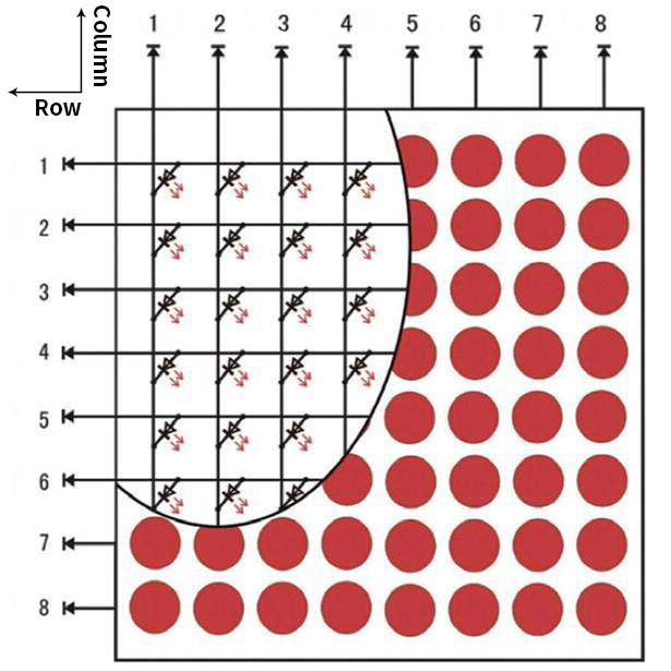
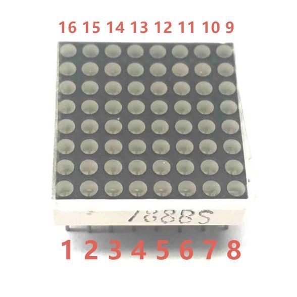
Every LED is installed on the cross point of row line and column line. When the voltage on a row line increases, and the voltage on the column line reduces, the LED on the cross point will light up. 8×8 dot matrix has 16 pins. Put the silk-screened side down and the numbers are 1, 8, 9 and 16 in anticlockwise order as marked below.
The definition inner pins are shown below:
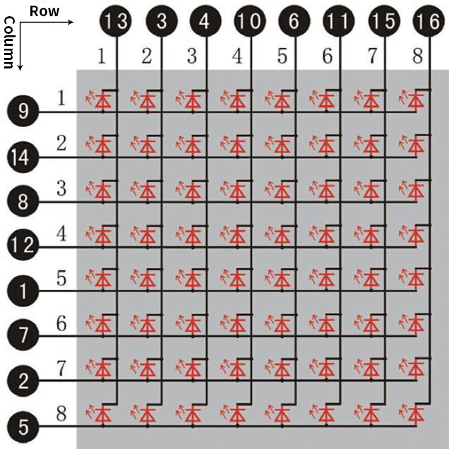
For instance, to light up the LED on row 1 and column 1, you should increase the voltage of pin 9 and reduce the voltage of pin 13.
HT16K33 8X8 Dot Matrix
The HT16K33 is a memory mapping and multi-purpose LED controller driver. The max. Display segment numbers in the device is 128 patterns (16 segments and 8 commons) with a 13*3 (MAX.) matrix key scan circuit. The software configuration features of the HT16K33 makes it suitable for multiple LED applications including LED modules and display subsystems. The HT16K33 is compatible with most microcontrollers and communicates via a two-line bidirectional I2C-bus.
The picture below is the working schematic of HT16K33 chip

We design the drive module of 8*8 dot matrix based on the above principle. We could control the dot matrix by I2C communication and two pins of microcontroller, according to the above diagram.
Specification:
Input voltage: 5V
Rated input frequency: 400KHZ
Input power: 2.5W
Input current: 500mA
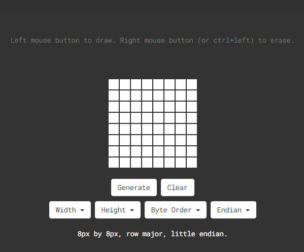
Introduction for Modulus Tool
The online version of dot matrix modulus tool: http://dotmatrixtool.com/
①Open the link to enter the following page.
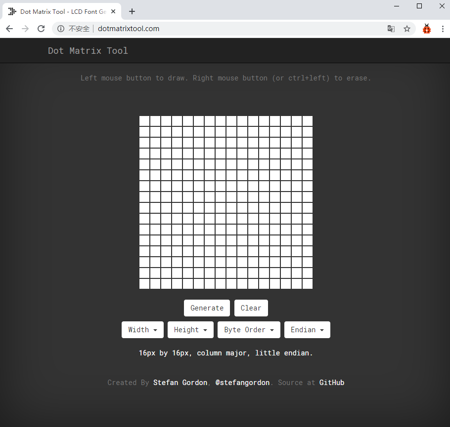
②The dot matrix is 8*8 in this project. So set the height to 8, width to 8; as shown below.
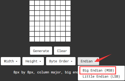
③Click Endian to select Big Endian(MSB)
③ Generate hexadecimal data from the pattern
As shown below, the left button of the mouse is for selection while the right is for canceling. Thus you could use them to draw the pattern you want, then click Generate, to yield the hexadecimal data needed.
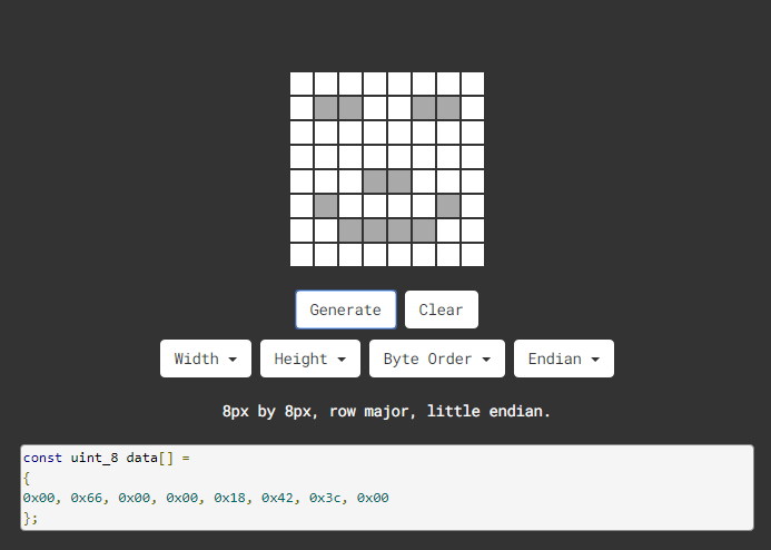
The generated hexadecimal code(0x00, 0x66, 0x00, 0x00, 0x18, 0x42, 0x3c, 0x00) is what will be displayed, so you need to save it for next procedure.
3. Wiring up:
8*8 Dot matrix display |
PCB Board |
|---|---|
G |
G |
5V |
5V |
SDA |
SDA |
SCL |
SCL |
4. Test Code:
The 8*8 dot matrix is controlled by GPIO21(SDA)and GPIO22(SCL)of the ESP32 board.
/*
 Project 03 8*8 Dot Matrix
 8*8 dot matrix screen to display patterns
*/
#include "HT16K33_Lib_For_ESP32.h"

#define SDA 21
#define SCL 22

ESP32_HT16K33 matrix = ESP32_HT16K33();

//The brightness values can be set from 1 to 15, with 1 darkest and 15 brightest
#define  A  15

byte result[8][8];
byte test1[8] = {0x70, 0x88, 0x84, 0x42, 0x42, 0x84, 0x88, 0x70};

void setup()
{
  matrix.init(0x70, SDA, SCL);//Initialize matrix
  matrix.showLedMatrix(test1,0,0);
  matrix.show();
}

void loop()
{
  for (int i = 0; i <= 7; i++)
  {
    matrix.setBrightness(i);
    delay(100);
  }
  for (int i = 7; i > 0; i--)
  {
    matrix.setBrightness(i);
    delay(100);
  }
}
5. Test Result
Upload the code to the ESP32 board(if the code can’t be uploaded, you can click and press Boot, as shown below
Power up by a USB cable, the 8*8 dot matrix display will show show “❤”pattern.
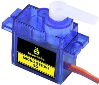
Project 04: Servo Rotation
1. Description:
There are two servos on the car. We take the servo connected to pin D9 as an example.
The servo is a motor that can rotate very accurately. It has been widely applied to toy cars, remote control helicopters, airplanes, robots and other fields. In this project, we will use the Nano motherboard to control the servo to spin.
2. Knowledge:
Servo motor is a position control rotary actuator. It mainly consists of a housing, a circuit board, a core-less motor, a gear and a position sensor. Its working principle is that the servo receives the signal sent by MCU or receiver and produces a reference signal with a period of 20ms and width of 1.5ms, then compares the acquired DC bias voltage to the voltage of the potentiometer and obtain the voltage difference output.
When the motor speed is constant, the potentiometer is driven to rotate through the cascade reduction gear, which leads that the voltage difference is 0, and the motor stops rotating. Generally, the angle range of servo rotation is 0° –180 °.
The rotation angle of servo motor is controlled by regulating the duty cycle of PWM (Pulse-Width Modulation) signal. The standard cycle of PWM signal is 20ms (50Hz). Theoretically, the width is distributed between 1ms-2ms, but in fact, it’s between 0.5ms-2.5ms. The width corresponds the rotation angle from 0° to 180°. But note that for different brand motors, the same signal may have different rotation angles.
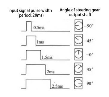
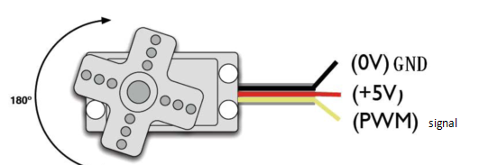
In general, servo has three lines in brown, red and orange. The brown wire is grounded, the red one is a positive pole line and the orange one is a signal line.
3. Wire up:
Servo |
PCB Board |
|---|---|
Brown |
G |
Red |
5V |
Orange |
S1(GPIO4) |
4. Test Code :
The servo for controlling the ultrasonic sensor is controlled by the GPIO4 of the ESP32 board.
/*
Project 04.2 Servo Rotation
the servo will rotate from 0 degrees to 180 degrees and then reverse the direction to make it rotate from 180 degrees to 0 degrees and repeat these actions in an endless loop.
*/
#include <ESP32Servo.h>

Servo myservo;  // create servo object to control a servo

int posVal = 0;    // variable to store the servo position
int servoPin = 4; // Servo motor pin

void setup() {
  myservo.setPeriodHertz(50);           // standard 50 hz servo
  myservo.attach(servoPin, 500, 2500);  // attaches the servo on servoPin to the servo object
}
void loop() {

  for (posVal = 0; posVal <= 180; posVal += 1) { // goes from 0 degrees to 180 degrees
    // in steps of 1 degree
    myservo.write(posVal);       // tell servo to go to position in variable 'pos'
    delay(15);                   // waits 15ms for the servo to reach the position
  }
  for (posVal = 180; posVal >= 0; posVal -= 1) { // goes from 180 degrees to 0 degrees
    myservo.write(posVal);       // tell servo to go to position in variable 'pos'
    delay(15);                   // waits 15ms for the servo to reach the position
  }
}
5. Test Result:
Place batteries in the car, and turn the power switch to ON end and power up.
Upload the code to the ESP32 board(if the code can’t be uploaded, you can click and press Boot, as shown below
Power up with a USB cable, the arm will rotate from 0° to 180°, then from 180° to 0°
Project 05: Motor Driving and Speed Control
1. Description:
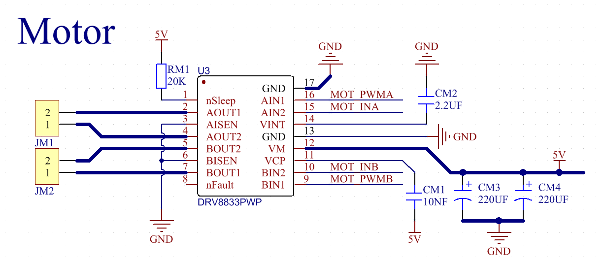
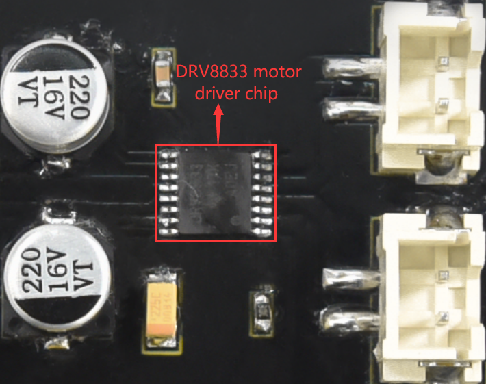
There are many ways to drive motors. This car uses the most commonly used DRV8833 motor driver chip, which provides a dual-channel bridge electric driver for toys, printers and other motor integration applications.
In this experiment, we use the DRV8833 motor driver chip on the expansion board to drive the two DC motors, and demonstrate the effect of forward, backward, left-turning, and right-turning.
2. Knowledge:
DRV8833 motor driver chip: Dual H-bridge motor driver with current control function, can drive two DC motors, one bipolar stepper motor, solenoid valve or other inductive loads. Each H-bridge includes circuitry to regulate or limit winding current.
An internal shutdown function with a fault output pin is used for over-current and short circuit protection, under-voltage lockout and over-temperature. A low-power sleep mode is also added. Let’s take a look at the schematic diagram of the DRV8833 motor driver chip driving two DC motors:
If you want to get insight to it, you can check the specification of this chip. Just browse it in the “Other_Important_Informations” folder.

3. Specification:
Input voltage of logic part: DC 5V
Input voltage of driving part : DC 5V
Working current of logic part: <30mA
Operating current of driving part: <2A
Maximum power dissipation: 10W (T=80℃)
Motor speed: 5V 200 rpm / min
Motor drive form: dual H-bridge drive
Control signal input level: high level 2.3V<Vin<5V, low level -0.3V<Vin<1.5V
Working temperature: -25~130℃
4. Drive the car to move
From the above diagram, the direction pin of the left motor is GPIO33; the speed pin is GPIO26; GPIO32 is the direction pin of the right motor; and GPIO25 is speed pin.
PWM drives the robot car. The PWM value is in the range of 0-255. The more the PWM value is set, the faster the rotation of the motor.
Function |
GPIO33 |
GPIO26(PWM) |
Left motor |
GPIO32 |
GPIO25(PW) |
Right motor |
|---|---|---|---|---|---|---|
forward |
LOW |
200 |
clockwise |
LOW |
200 |
clockwise |
Go back |
HIGH |
55 |
anticlockwise |
HIGH |
55 |
anticlockwise |
Turn left |
HIGH |
200 |
anticlockwise |
LOW |
200 |
clockwise |
Turn right |
LOW |
200 |
clockwise |
HIGH |
200 |
anticlockwise |
Stop |
LOW |
0 |
stop |
LOW |
0 |
stop |
5. Test Code:
/*
Project 05 Motor drive and speed regulation
Motor moves forward, backward, left and right
*/
#define left_ctrl 33 //define the direction control pin(rgpio33) of the left motor
#define left_pwm 26 //define PWM control pins of the left motor as gpio25
#define right_ctrl 32 //Define the direction control pin of the right motor as gpio32
#define right_pwm 25 //define PWM control pins of the right motor as gpio25
void setup()
{
pinMode(left_ctrl,OUTPUT); //set control pins of the left motor to OUTPUT
ledcAttach(left_pwm, 1200, 8); //Set the frequency of left_pwm pin to 1200, PWM resolution to 8 that duty cycle is 256.
pinMode(right_ctrl,OUTPUT);//set direction control pins of the right motor to OUTPUT..
ledcAttach(right_pwm, 1200, 8); //Set the frequency of right_pwm pin to 1200, PWM resolution to 8 that duty cycle is 256.
}
void loop()
{
//front
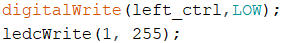
digitalWrite(left_ctrl,LOW); // set direction control pins of the left motor to LOW.
ledcWrite(left_pwm, 200); // the left motor outputs PWM 200
digitalWrite(right_ctrl,LOW); // set control pins of the right motor to LOW.
ledcWrite(right_pwm, 200); // the right motor outputs PWM 200
delay(2000);//delay in 2s
//back
digitalWrite(left_ctrl,HIGH); // set direction control pins of the left motor to HIGH.
ledcWrite(left_pwm, 55); // the left motor outputs PWM 55
digitalWrite(right_ctrl,HIGH); // set control pins of the right motor to HIGH.
ledcWrite(right_pwm, 55); // the right motor outputs PWM 55
delay(2000);//delay in 2s
//left
digitalWrite(left_ctrl,HIGH); // set direction control pins of the left motor to HIGH..
ledcWrite(left_pwm, 55); // the left motor outputs PWM 55.
digitalWrite(right_ctrl,LOW); // set control pins of the right motor to LOW.
ledcWrite(right_pwm, 200); // the right motor outputs PWM 200.
delay(2000);//delay in 2s
//right
digitalWrite(left_ctrl,LOW); // set direction control pins of the left motor to LOW.
ledcWrite(left_pwm, 200); // the left motor outputs PWM 200.
digitalWrite(right_ctrl,HIGH); // set control pins of the right motor to HIGH..
ledcWrite(right_pwm, 55); // the right motor outputs PWM 55
delay(2000);//delay in 2s
//stop
digitalWrite(left_ctrl,LOW);// set direction control pins of the left motor to LOW.
ledcWrite(left_pwm, 0); // the left motor outputs PWM 0.
digitalWrite(right_ctrl,LOW);// set control pins of the right motor to LOW.
ledcWrite(right_pwm, 0); // the right motor outputs PWM 0
delay(2000);//delay in 2s
}
6. Test Result
Place batteries in the car, and turn the power switch to ON end and power up.
Upload the code to the ESP32 board(if the code can’t be uploaded, you can click and press Boot, as shown below
Then the car moves forward for 2s, backward for 2s, turns left for 2s and right for 2s, stops for 2s.
7. Speed regulation
HIGH is equivalent to a PWM value of 255, and 50 is a PWM value that can be adjusted. The difference in this code is 200. The larger the upper and lower difference is, the faster the motor rotates. We can adjust the motor speed by adjusting the PWM value. If 50 is set to 0, the upper and lower difference becomes 255, and the motor speed reaches the maximum; if 50 is set to 255, the upper and lower difference becomes 0, the motor speed is 0, and the motor does not rotate. When the upper and lower difference values are positive, the motor reverses.
LOW is equivalent to a PWM value of 0, and 255 is a PWM value that can be adjusted. The difference in this code is 255. The larger the upper and lower difference is, the faster the motor rotates. We can adjust the motor speed by adjusting the PWM value. If 255 is set to 100, the upper and lower difference becomes 100, and the motor speed slows down; if the upper and lower difference is 255, the motor speed reaches the maximum; if 255 is set to 0, the upper and lower difference becomes 0, and the motor does not work. turned. When the upper and lower difference values are negative, the motor rotates forward.
Project 06: Ultrasonic Sensor
1. Description:
There is an ultrasonic sensor on the car. It is a very affordable distance-measuring sensor.
The ultrasonic sensor sends a high-frequency ultrasonic signal that human hearing can’t hear. When encountering obstacles, these signals will be reflected back immediately. After receiving the returned information, the distance between the sensor and the obstacle will be calculated by judging the time difference between the transmitted signal and the received signal. It is mainly used for object avoidance and ranging in various robotics projects.
In this experiment, we use an ultrasonic sensor to measure distance and print the data on a serial monitor.
2. Knowledge:
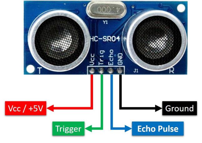
The HC-SR04 ultrasonic sensor uses sonar to determine distance to an object like what bats do. It offers excellent non-contact range detection with high accuracy and stable readings in an easy-to-use package. It comes complete with ultrasonic transmitter and receiver modules.
The HC-SR04 or the ultrasonic sensor is being used in a wide range of electronics projects for creating obstacle detection and distance measuring application as well as various other applications. Here we have brought the simple method to measure the distance with Arduino and ultrasonic sensor and how to use ultrasonic sensor with Arduino.
Use method and timing chart of ultrasonic module:
Setting the delay time of Trig pin of SR04 to 10μs at least, which can trigger it to detect distance.
After triggering, the module will automatically send eight 40KHz ultrasonic pulses and detect whether there is a signal return. This step will be completed automatically by the module.
If the signal returns, the Echo pin will output a high level, and the duration of the high level is the time from the transmission of the ultrasonic wave to the return.
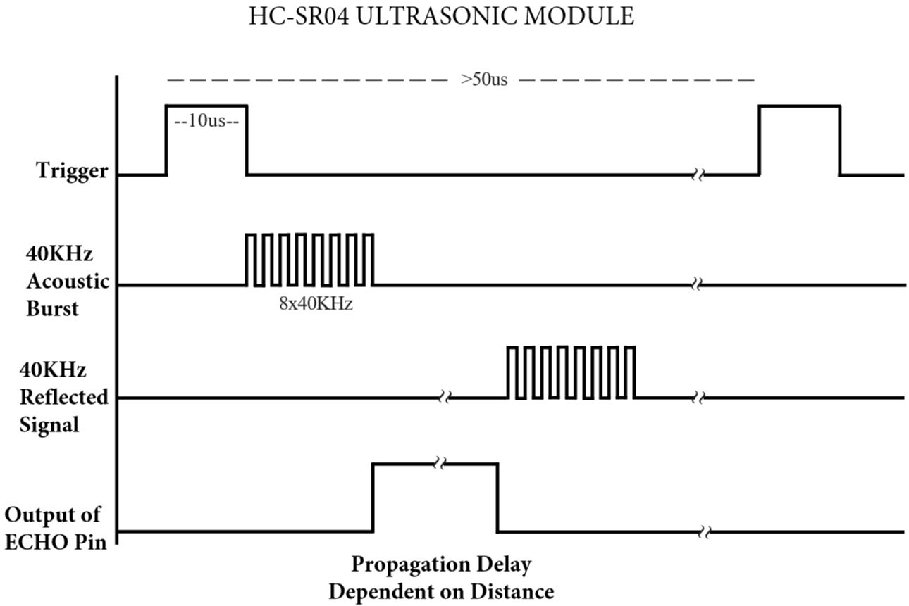
Time=Echo pulse width, unit: us
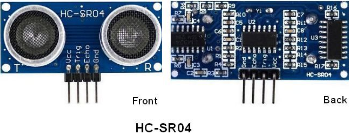
The HC-SR04 ultrasonic sensor has four pins: Vcc, Trig, Echo and GND.
The Vcc pin provides power generating ultrasonic pulses and is connected to Vcc/+5V. The GND pin is grounded/GND.
The Trig pin is where the Arduino sends a signal to start the ultrasonic pulse. The Echo pin is where the ultrasonic sensor sends information about the duration of the ultrasonic pulse stroke to the Arduino control board.
3. Wiring Up
Ultrasonic Sensor |
PCB Board |
|---|---|
Vcc |
5V |
Trig |
S2(GPIO5) |
Echo |
S1(GPIO18) |
Gnd |
G |
4. Test Code:
The pin Trig and Echo of the ultrasonic sensor are controlled by the GPIO5 and GPIO18 of the ESP32 board.
/*
Project 06 Ultrasonic Sensor
Ultrasonic detection of distance from objects
*/
#define trigPin 5 // define trigPin gpio5.
#define echoPin 18 // define echoPin gpio18.
#define MAX_DISTANCE 700 // Maximum sensor distance is rated at 400-500cm.
//timeOut= 2*MAX_DISTANCE /100 /340 *1000000 = MAX_DISTANCE*58.8
float timeOut = MAX_DISTANCE * 60;
int soundVelocity = 340; // define sound speed=340m/s
void setup() {
 pinMode(trigPin,OUTPUT);// set trigPin to output mode
 pinMode(echoPin,INPUT); // set echoPin to input mode
 Serial.begin(115200); // Open serial monitor at 115200 baud to see ping results.
}
void loop() {
 delay(100); // Wait 100ms between pings (about 20 pings/sec).
 Serial.printf("Distance: ");
 Serial.print(getSonar()); // Send ping, get distance in cm and print result
 Serial.println("cm");
}
float getSonar() {
 unsigned long pingTime;
 float distance;
 // make trigPin output high level lasting for 10us to trigger HC_SR04
  digitalWrite(trigPin, HIGH);
 delayMicroseconds(10);
 digitalWrite(trigPin, LOW);
 // Wait HC-SR04 returning to the high level and measure out this waiting time
 pingTime = pulseIn(echoPin, HIGH, timeOut);
 // calculate the distance according to the time
 distance = (float)pingTime * soundVelocity / 2 / 10000;
 return distance; // return the distance value
}
5. Test Result
Upload the code to the ESP32 board(if the code can’t be uploaded, you can click and press Boot, as shown below.
Power up with a USB cable, open the monitor and set baud to 115200. When you move an object in front of the ultrasonic sensor, it will detect the distance and the serial monitor will show the distance value.
Project 07: Follow Me
1. Description:
In the above experiments, we have learned about the 8*8 dot matrix, motor drivers and speed regulation, ultrasonic sensors, servos and other hardware. In this experiment, we will combine them to create a follow car with the ultrasonic sensor. The can can follow an object to move through measuring distance.
2. Working Principle:

3. Flow Chart:

4. Test Code:
/*
Project 07: follow me
Car follows the object
*/
#include <ESP32Servo.h>
//motor
#define left_ctrl  33  //define direction control pins of the left motor as gpio33
#define left_pwm  26   //define PWM control pins of the left motor as gpio26.
#define right_ctrl  32 //define direction control pins of the right motor as gpio32.
#define right_pwm  25  //define PWM control pins of the right motor as gpio25

//ultrasonic sensor
#define TRIG_PIN 5 // set signals input of the ultrasonic sensor to gpio5.
#define ECHO_PIN 18 //set signals output of the ultrasonic sensor to gpio18.
long distance; //define distance variables

//servo
const int servoPin = 4;//set the pin of the servo to gpio4.
Servo myservo;  // create servo object to control a servo

void setup() {
  pinMode(left_ctrl,OUTPUT); //set control pins of the left motor to OUTPUT
  ledcAttach(left_pwm, 1200, 8); //Set the frequency of left_pwm pin to 1200, PWM resolution to 8 that duty cycle is 256.
  pinMode(right_ctrl,OUTPUT);//set direction control pins of the right motor to OUTPUT..
  ledcAttach(right_pwm, 1200, 8); //Set the frequency of right_pwm pin to 1200, PWM resolution to 8 that duty cycle is 256.

  pinMode(TRIG_PIN,OUTPUT);//set TRIG_PIN to OUTPUT.
  pinMode(ECHO_PIN,INPUT);//set ECHO_PIN to INPUT.

  myservo.setPeriodHertz(50);           // standard 50 hz servo
  myservo.attach(servoPin, 500, 2500);  // attaches the servo on servoPin to the servo object.
  myservo.write(90);  // the initial angle of the servo is set to 90° .
  delay(300);
}

void loop() {
  distance = checkdistance();//Get the distance measured by the ultrasonic sensor
  Serial.print(distance);//Send a pulse, calculate the distance in centimeters and print the result.
  Serial.println("cm");
  if(distance<8)//if distance is less than 8
  {
    back();//back
  }
  else if((distance>=8)&&(distance<13))//if 8≤distance<13
  {
    Stop();//stop
  }
  else if((distance>=13)&&(distance<35))//if 13≤distance<35.
  {
    front();//follow
  }
  else//
  {
    Stop();//stop
  }
}

float checkdistance() {
  digitalWrite(TRIG_PIN, LOW);
  delayMicroseconds(2);
  digitalWrite(TRIG_PIN, HIGH);
  delayMicroseconds(10);
  digitalWrite(TRIG_PIN, LOW);
  float distance = pulseIn(ECHO_PIN, HIGH) / 58.00;
  delay(10);
  return distance;
}

void front()//define the state of going forward
{
  digitalWrite(left_ctrl,LOW); //set direction control pins of the left motor to LOW.
  ledcWrite(left_pwm, 150); //the left motor outputs PWM 150
  digitalWrite(right_ctrl,LOW); //set control pins of the right motor to LOW.
  ledcWrite(right_pwm, 150); //the right motor outputs PWM 150
}
void back()//define the state of going back
{
  digitalWrite(left_ctrl,HIGH); //set direction control pins of the left motor to HIGH..
  ledcWrite(left_pwm, 100); //the left motor outputs PWM 100
  digitalWrite(right_ctrl,HIGH); //set control pins of the right motor to HIGH..
  ledcWrite(right_pwm, 100); //the right motor outputs PWM 100
}
void Stop()//define state of stopping
{
  digitalWrite(left_ctrl,LOW);//set direction control pins of the left motor to LOW.
  ledcWrite(left_pwm, 0); //the left motor outputs PWM 0.
  digitalWrite(right_ctrl,LOW);//set control pins of the right motor to LOW.
  ledcWrite(right_pwm, 0); //the right motor outputs PWM 0
}
5. Test Result
Upload the code to the ESP32 board(if the code can’t be uploaded, you can click and press Boot, as shown below.
Place batteries in the car and turn the power switch to ON end and power up. Then the car will follow the obstacle to move.
Project 08: Avoid obstacles
1. Description:
In this project, we will take advantage of the ultrasonic sensor to detect the distance away from the obstacle so as to avoid them
2. Working Principle:
3. Flow Chart:

4. Test Code:
/*
Project 08: avoid obstacles
*/
#include <ESP32Servo.h>
//motor
#define left_ctrl  33  //define direction control pins of the left motor as gpio33
#define left_pwm  26   //define PWM control pins of the left motor as gpio26.
#define right_ctrl  32 //define direction control pins of the right motor as gpio32.
#define right_pwm  25  //define PWM control pins of the right motor as gpio25

//ultrasonic sensor
#define TRIG_PIN 5 // Define the signal input of the ultrasonic sensor as gpio5.
#define ECHO_PIN 18 // Define the signal output of the ultrasonic sensor as gpio18.
long distance,a1,a2;//define three distance variables

//servo
const int servoPin = 4; //set the pin of the servo to gpio4.
Servo myservo;  // create servo object to control a servo

void setup() {
  pinMode(left_ctrl,OUTPUT); //set control pins of the left motor to OUTPUT
  ledcAttach(left_pwm, 1200, 8); //Set the frequency of left_pwm pin to 1200, PWM resolution to 8 that duty cycle is 256.
  pinMode(right_ctrl,OUTPUT); //set direction control pins of the right motor to OUTPUT..
  ledcAttach(right_pwm, 1200, 8); //Set the frequency of right_pwm pin to 1200, PWM resolution to 8 that duty cycle is 256.

  pinMode(TRIG_PIN,OUTPUT); //set TRIG_PIN to OUTPUT.
  pinMode(ECHO_PIN,INPUT); //set ECHO_PIN to INPUT.

  myservo.setPeriodHertz(50);           // standard 50 hz servo
  myservo.attach(servoPin, 500, 2500);  // attaches the servo on servoPin to the servo object.
  myservo.write(90);
  delay(500);
}

void loop()
 {
  avoid();//obstacle avoidance
}

float checkdistance() {
  digitalWrite(TRIG_PIN, LOW);
  delayMicroseconds(2);
  digitalWrite(TRIG_PIN, HIGH);
  delayMicroseconds(10);
  digitalWrite(TRIG_PIN, LOW);
  float distance = pulseIn(ECHO_PIN, HIGH) / 58.00;
  delay(10);
  return distance;
}

void avoid()
{
  distance = checkdistance(); //Get the value of ultrasonic distance
  Serial.println(distance);
  if((distance < 10)&&(distance != 0))//if 0<distance<10
  {
    car_Stop();//stop
    delay(100);
    myservo.write(180);  //the servo turns to 180°.
    delay(500);
    a1=checkdistance();//Measuring distance
    delay(100);
    myservo.write(0); //the servo turns to 0°.
    delay(500);
    a2=checkdistance();//Measuring distance
    delay(100);

    if(a1 > a2)//
    {
      car_left();//turn left
      delay(100);
      myservo.write(90); //the initial angle of the servo is set to 90° .
      delay(500);
    }
    else//if left distance < right distance
    {
      car_right();//turn right
      delay(100);
      myservo.write(90); //the initial angle of the servo is set to 90° .
      delay(500);
    }
  }
  else//
  {
    car_front();//go forward
  }
}

void car_front()//define the state of going forward
{
  digitalWrite(left_ctrl,LOW); //set direction control pins of the left motor to LOW.
  ledcWrite(left_pwm, 100); //the left motor outputs PWM 100
  digitalWrite(right_ctrl,LOW); //set control pins of the right motor to LOW.
  ledcWrite(right_pwm, 100); //the right motor outputs PWM 100
}
void car_back()//define the state of going back
{
  digitalWrite(left_ctrl,HIGH); //set direction control pins of the left motor to HIGH..
  ledcWrite(left_pwm, 100); //the left motor outputs PWM 100
  digitalWrite(right_ctrl,HIGH); //set control pins of the right motor to HIGH..
  ledcWrite(right_pwm, 100); //the right motor outputs PWM 100
}
void car_left()//define the state of turning left
{
  digitalWrite(left_ctrl,HIGH); //set direction control pins of the left motor to HIGH..
  ledcWrite(left_pwm, 100); //the left motor outputs PWM 100
  digitalWrite(right_ctrl,LOW); //set control pins of the right motor to LOW.
  ledcWrite(right_pwm, 100); //the right motor outputs PWM 100
}
void car_right()//define the state of turning right
{
  digitalWrite(left_ctrl,LOW); //set direction control pins of the left motor to LOW.
  ledcWrite(left_pwm, 100); //the left motor outputs PWM 100
  digitalWrite(right_ctrl,HIGH); //set control pins of the right motor to HIGH..
  ledcWrite(right_pwm, 100); //the right motor outputs PWM 100
}
void car_Stop()//define the state of stopping
{
  digitalWrite(left_ctrl,LOW);//set direction control pins of the left motor to LOW.
  ledcWrite(left_pwm, 0); //the left motor outputs PWM 0
  digitalWrite(right_ctrl,LOW);//set control pins of the right motor to LOW.
  ledcWrite(right_pwm, 0); //the right motor outputs PWM 0
}
5. Test Result
Upload the code to the ESP32 board(if the code can’t be uploaded, you can click and press Boot, as shown below
Place batteries in the car and power up. Then the car can automatically dodge obstacles
Project 09: Line Tracking Sensor
1. Description:
There are two IR line tracking sensors on the car. They are actually two pairs of ST188L3 infrared tubes and used to detect black and white lines. In this project, we will make a line tracking car
In this experiment, we use ST188L3 infrared tubes to detect black and white lines, then print the data on the serial monitor.
2. Knowledge:
Infrared line tracking:
The IR line tracking sensor boasts a pair of ST188L3 infrared tubes. ST188L3 tubes has an infrared emitting diode and a receiver tube. When the emitting diode emits an infrared signal then received by the receiving tube after being reflected by the white object. Once the receiving tube receives the signal, the output terminal will output a low level (0); when the infrared emitting diode emits an infrared signal, and the infrared signal is absorbed by the black object, a high level (1) will be output, thus realizing the function of detecting signals through infrared rays.
Warning: Reflective optical sensors (including IR line tracking sensors) shouldn’t be applied under sunlight as there is a lot of invisible light such as infrared and ultraviolet.
Values detected by the line tracking sensor are shown in the table.
The value will be 1 if detecting black or no objects and the value 0 will appear if detecting white objects.
he detected black object or no object represents 1, and the detected white object represents 0.
Left |
Right |
Value(Binary ) |
|---|---|---|
0 |
0 |
00 |
0 |
1 |
01 |
1 |
0 |
10 |
1 |
1 |
11 |
3. Test Code:
The line tracking sensors of the PCB board are controlled by GPIO17 and GPIO16 of the ESP32 board.
/*
Project 09: Line Tracking Sensor
*/
#define tracking_left  17  //define the pin of the left sensor as gpio17
#define tracking_right  16  //define the pin of the right sensor as gpio16
int L_val,R_val; //define two variables of two sensors

void setup() {
 Serial.begin(115200); //set baud rate to 115200
 pinMode(tracking_left, INPUT); //set pins of the left sensor to INPUT
 pinMode(tracking_right, INPUT); //set pins of the right sensor to INPUT
}

void loop() {
 L_val = digitalRead(tracking_left); //read the value of the left sensor
 R_val = digitalRead(tracking_right); //read the value of the right sensor
 Serial.print("L_val: "); //serial print L_val
 Serial.print(L_val); //serial prints L_val
 Serial.print("    "); //serial prints space key
 Serial.print("R_val: "); //serial prints R_val
 Serial.println(R_val); //serial prints the R_val
 delay(300); //delay in 0.3s
}
4. Test Result
Upload the code to the ESP32 board(if the code can’t be uploaded, you can click and press Boot, as shown below
Power on with a USB cable, open the serial monitor and set the baud rate to 115200.
Put a black thing under the line tracking sensor of the car and move it, you will see different indicators light up, and at the same time you will see the value on the serial monitor.
The sensitivity can be adjusted by rotating the potentiometer. When the indicator light is adjusted to the critical point of on and off state, the sensitivity is the highest.
Project 10: Line Tracking
1. Description:
We’ve introduced the knowledge of motor drivers, speed regulation, and infrared line tracking. In this experiment, the car will perform different actions according to the values transmitted by the infrared tracking.
2. Working Principle:
Left |
Right |
Value(Binary ) |
State |
|---|---|---|---|
0 |
0 |
00 |
Stop |
0 |
1 |
01 |
Turn right |
1 |
0 |
10 |
Turn left |
1 |
1 |
11 |
Move forward |
3. Flow Chart:
4. Test Code:
/*
Project 10: Line Tracking
*/
#include <ESP32Servo.h>
//motor
#define left_ctrl  33  //define direction control pins of the left motor as gpio33
#define left_pwm  26   //define PWM control pins of the left motor as gpio26
#define right_ctrl  32 //define direction control pins of the right motor as gpio32
#define right_pwm  25  //define the PWM control pin of the right motor as gpio25

//IR line tracking
#define tracking_left  17  //set the pin of the left line tracking sensor to gpio17
#define tracking_right  16  //set the pin of the right line tracking sensor to gpio16
int L_val,R_val;//Define two variables

//servo
const int servoPin = 4;//set the pin of the servo to gpio4.
Servo myservo;  // create servo object to control a servo

void setup() {
  pinMode(left_ctrl,OUTPUT); //set control pins of the left motor to OUTPUT
  ledcAttach(left_pwm, 1200, 8); //Set the frequency of left_pwm pin to 1200, PWM resolution to 8 that duty cycle is 256.
  pinMode(right_ctrl,OUTPUT);//set direction control pins of the right motor to OUTPUT..
  ledcAttach(right_pwm, 1200, 8); //Set the frequency of right_pwm pin to 1200, PWM resolution to 8 that duty cycle is 256.

  pinMode(tracking_left, INPUT); //Set right pins of the left sensor to input
  pinMode(tracking_right, INPUT); //Set right pins of the right sensor to input

  myservo.setPeriodHertz(50);           // standard 50 hz servo
  myservo.attach(servoPin, 500, 2500);  // attaches the servo on servoPin to the servo object.
  myservo.write(90);  // the initial angle of the servo is set to 90° .
  delay(300);
}

void loop()
{
  tracking(); //run main programs
}

void tracking()
{
  L_val = digitalRead(tracking_left);//read the value of the left line tracking sensor
  R_val = digitalRead(tracking_right);//read the value of the right line tracking sensor
  if((L_val == 1)&&(R_val == 1))//if both of sensors detect black lines
  {
    front();//go forward
  }
  else if((L_val == 1)&&(R_val == 0))//if only the left sensor detects black lines
  {
    left();//turn left
  }
  else if((L_val == 0)&&(R_val == 1))//if only the right sensor detects black lines
  {
    right();//turn right
  }
  else//if none of sensors detects black lines
  {
    Stop();//stop
   }
}

void front()//define the state of going forward
{
  digitalWrite(left_ctrl,LOW); //set direction control pins of the left motor to LOW.
  ledcWrite(left_pwm, 130); //the left motor outputs PWM 130
  digitalWrite(right_ctrl,LOW); //set control pins of the right motor to LOW.
  ledcWrite(right_pwm, 130); //the right motor outputs PWM 130
}
void left()//define the state of turning left
{
  digitalWrite(left_ctrl,HIGH); //set direction control pins of the left motor to HIGH..
  ledcWrite(left_pwm, 135); //the left motor outputs PWM 135
  digitalWrite(right_ctrl,LOW); //set control pins of the right motor to LOW.
  ledcWrite(right_pwm, 80); //the right motor outputs PWM 80
}
void right()//define the state of turning right
{
  digitalWrite(left_ctrl,LOW); //set direction control pins of the left motor to LOW.
  ledcWrite(left_pwm, 80); //the left motor outputs PWM 80
  digitalWrite(right_ctrl,HIGH); //set control pins of the right motor to HIGH..
  ledcWrite(right_pwm, 135); //the right motor outputs PWM 135
}
void Stop()//define the state of stopping
{
  digitalWrite(left_ctrl,LOW);//set direction control pins of the left motor to LOW.
  ledcWrite(left_pwm, 0); //the left motor outputs PWM 0
  digitalWrite(right_ctrl,LOW);//set control pins of the right motor to LOW.
  ledcWrite(right_pwm, 0); //the right motor outputs PWM 0
}
5. Test Result
Upload the code to the ESP32 board(if the code can’t be uploaded, you can click and press Boot, as shown below
Place batteries in the car, turn the power switch to ON end and power up.
Then the car will perform different functions via values sent by line tracking sensors
Project 11: Photosensor
1. Description:
There are two photoresistors on the car. They can vary with the light intensity and send information to the Nano board to control the car.
Photoresistors can determine and conduct the car to move by detecting light.
In this experiment, we will learn the working principle of the photoresistor
2. Knowledge:
Photoresistor:
It mainly uses a photosensitive resistance element whose resistance varies from the light intensity. The signal terminal of the sensor is connected to the analog port of the microcontroller. When the light is stronger, the analog value at the analog port will increase; on the contrary, when the light intensity is weaker, the analog value of the microcontroller will reduce. In this way, the corresponding analog value can reflect the ambient light intensity.
3. Wire up:
Through the wiring-up diagram, signal pins of two photoresistors are connected to GPIO34 and GPIO35 of the ESP32 board.
For the following experiment, we use the photoresistor connected to GPIO34 to finish experiments. First, let’s read analog values.
Left photoresistor |
PCB board |
|---|---|
G |
G |
V |
V |
S |
S(GPIO34) |
4. Test Code:
The left photoresistor is controlled by the GPIO34 of the ESP32 board.
/*
Project 11: Photosensor
*/
#define PHOTOSENSITIVE_PIN 34 //Define the pins that ESP32 reads photosensitive
int photosensitiveADC;        //Defines a variable to store ADC values

void setup()
{
  pinMode(PHOTOSENSITIVE_PIN, INPUT);//Configure the pins for input mode
  Serial.begin(115200);          //Initialize the serial port and set the baud rate to 115200
}

void loop()
{
  photosensitiveADC = analogRead(PHOTOSENSITIVE_PIN);//Read the photosensitive resistance value
  Serial.print("photosensitiveADC: ");
  Serial.println(photosensitiveADC);         //Print photosensitive resistance value
  delay(500);
}
5. Test Result
Upload the code to the ESP32 board ,if the code can’t be uploaded, you can click and press Boot, as shown below.
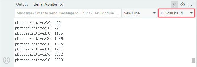
Power up with a USB cable, open the serial monitor and set baud rate to 115200.
When the light intensifies, the analog value will get increased; on the contrary, the analog value will get reduced.
Project 12: Light Following Car
1. Description:
We have learned the working principle of photoresistor, motor and speed regulation. In this experiment, we will use a photoresistor to detect the intensity of light as as to achieve the light following effect.
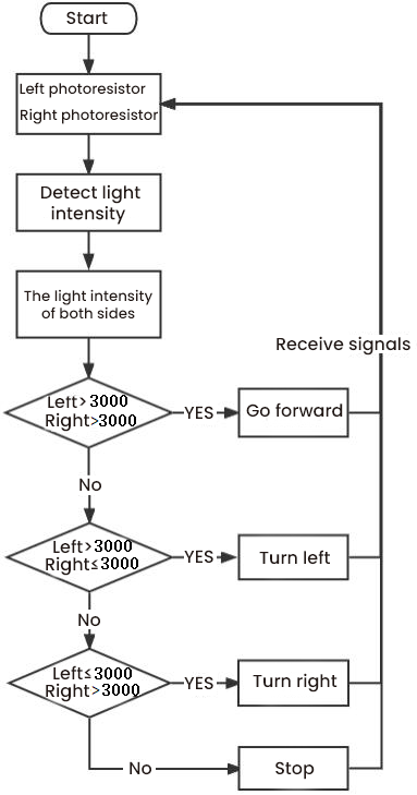
2. Working Principle:
Analog value of the left sensor |
Analog value of the right sensor |
Function |
|---|---|---|
>3000 |
>3000 |
Move forward |
>3000 |
≤3000 |
Move to left |
≤3000 |
>3000 |
Move to right |
<3000 |
<3000 |
Stop |
3. Wiring up:
Left Photoresistor |
PCB Board |
Right photoresistor |
PCB Board |
|
|---|---|---|---|---|
G |
G |
G |
G |
|
V |
V |
V |
V |
|
S |
S(GPIO34) |
S |
S(GPIO35) |
4. Flow Chart:
5. Test Code:
The left and right photoresistors are controlled by GPIO34 and GPIO35 of the ESP32 board.
/*
Project 12:Light Following Car
*/
#include <ESP32Servo.h>
//motor
#define left_ctrl  33  //define direction control pins of the left motor as gpio33
#define left_pwm  26   //define PWM control pins of the left motor as gpio26.
#define right_ctrl  32 //define direction control pins of the right motor as gpio32.
#define right_pwm  25  //define PWM control pins of the right motor as gpio25

//photoresistors
#define light_L_Pin  34   //define the pins of the left photoresistor as gpio34
#define light_R_Pin  35   //define the pins of the right photoresistor as gpio35
int left_light;
int right_light;

//servo
const int servoPin = 4;//set the pin of the servo to gpio4.
Servo myservo;  // create servo object to control a servo

void setup(){
  Serial.begin(115200); //set baud rate to 115200.
  pinMode(light_L_Pin, INPUT); //set pins of the left sensor to INPUT
  pinMode(light_R_Pin, INPUT); //set pins of the right sensor to INPUT

  pinMode(left_ctrl,OUTPUT); //set control pins of the left motor to OUTPUT
  ledcAttach(left_pwm, 1200, 8); //Set the frequency of left_pwm pin to 1200, PWM resolution to 8 that duty cycle is 256.
  pinMode(right_ctrl,OUTPUT);//set direction control pins of the right motor to OUTPUT..
  ledcAttach(right_pwm, 1200, 8); //Set the frequency of right_pwm pin to 1200, PWM resolution to 8 that duty cycle is 256.

  myservo.setPeriodHertz(50);           // standard 50 hz servo
  myservo.attach(servoPin, 500, 2500);  // attaches the servo on servoPin to the servo object.
  myservo.write(90);  // the initial angle of the servo is set to 90° .
  delay(300);
}

void loop(){
  left_light = analogRead(light_L_Pin);//Read the value of the left photoresistor
  right_light = analogRead(light_R_Pin);//Read the value of the right photoresistor
  Serial.print("left_light_value = ");
  Serial.println(left_light);
  Serial.print("right_light_value = ");
  Serial.println(right_light);
  if (left_light > 3000 && right_light > 3000) //detect ranges of left and right photoresistors
  {
    Car_front(); //go forward
  }
  else if (left_light > 3000 && right_light <= 3000)  //detect ranges of left and right photoresistors
  {
    Car_left(); //turn left
  }
  else if (left_light <= 3000 && right_light > 3000) //detect ranges of left and right photoresistors
  {
    Car_right(); //turn right
  }
  else  //
  {
    Car_Stop(); //stop
  }
}

void Car_front()
{
  digitalWrite(left_ctrl,LOW); //set direction control pins of the left motor to LOW.
  ledcWrite(left_pwm, 150); //the left motor outputs PWM 150
  digitalWrite(right_ctrl,LOW); //set control pins of the right motor to LOW.
  ledcWrite(right_pwm, 150); //the right motor outputs PWM 150
}
void Car_left()
{
  digitalWrite(left_ctrl,HIGH); //set direction control pins of the left motor to HIGH..
  ledcWrite(left_pwm, 150); //the left motor outputs PWM 150
  digitalWrite(right_ctrl,LOW); //set control pins of the right motor to LOW.
  ledcWrite(right_pwm, 150); //the right motor outputs PWM 150
}
void Car_right()
{
  digitalWrite(left_ctrl,LOW); //set direction control pins of the left motor to LOW.
  ledcWrite(left_pwm, 150); //the left motor outputs PWM 150
  digitalWrite(right_ctrl,HIGH); //set control pins of the right motor to HIGH..
  ledcWrite(right_pwm, 150); //the right motor outputs PWM 135
}
void Car_Stop()
{
  digitalWrite(left_ctrl,LOW);//set direction control pins of the left motor to LOW.
  ledcWrite(left_pwm, 0); //the left motor outputs PWM 0
  digitalWrite(right_ctrl,LOW);//set control pins of the right motor to LOW.
  ledcWrite(right_pwm, 0); //the right motor outputs PWM 0
}
6. Test Result
Upload the code to the ESP32 board(if the code can’t be uploaded, you can click and press Boot, as shown below.
Place batteries in the battery holder, turn the power switch to the ON end and power up. Then the car will follow the light to move.
Project 13: IR Remote Control
1. Description:
Infrared remote controls are everywhere in daily life. It is used to control various home appliances, such as TV, speakers, video recorders and satellite signal receivers.
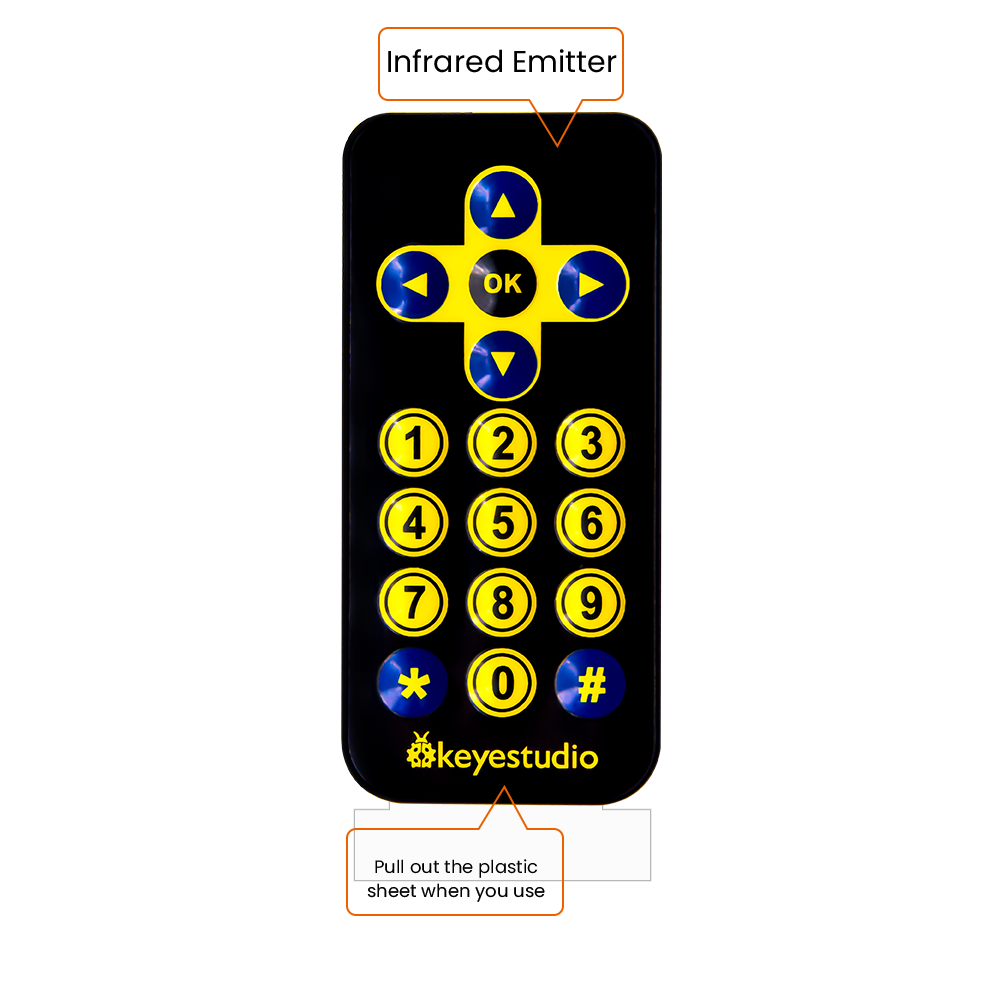
The remote control is composed of an IR emitter, an IR receiver and a decoding MCU. In this project, we will make a IR remote control car.
In this experiment, we will combine the IR receiver and the IR remote control to read key values and show them on the serial monitor.
2. Knowledge:
IR Remote Control:
It is a device with buttons. When the key is pressed, IR signals will be sent.
Infrared remote control technology is widely used, such as TVs, air conditioners and so on. And it can control air conditioners and TVs
The infrared remote control adopts NEC coding, and the signal period is 110ms.
The remote control is shown below:
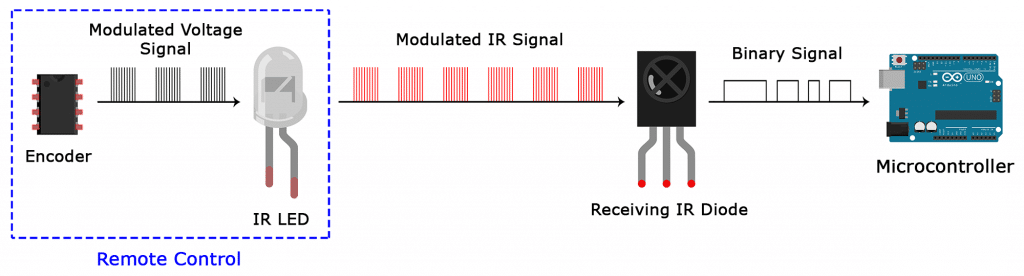
Infrared (IR) receiver:
It can receive infrared light and be used to detect the infrared signal emitted by the infrared remote control.
It can demodulate the received infrared light signal and convert it back to binary, and then transmit the information to the microcontroller.
NEC Infrared communication protocol:
NEC Protocol
To my knowledge the protocol I describe here was developed by NEC (Now Renesas). I’ve seen very similar protocol descriptions on the internet, and there the protocol is called Japanese Format.
I do admit that I don’t know exactly who developed it. What I do know is that it was used in my late VCR produced by Sanyo and was marketed under the name of Fisher. NEC manufactured the remote control IC.
This description was taken from my VCR’s service manual. Those were the days, when service manuals were filled with useful information!
Features
8 bit address and 8 bit command length.
Extended mode available, doubling the address size.
Address and command are transmitted twice for reliability.
Pulse distance modulation.
Carrier frequency of 38kHz.
Bit time of 1.125ms or 2.25ms.
Modulation
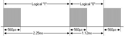
The NEC protocol uses pulse distance encoding of the bits. Each pulse is a 560µs long 38kHz carrier burst (about 21 cycles). A logical “1” takes 2.25ms to transmit, while a logical “0” is only half of that, being 1.125ms. The recommended carrier duty-cycle is 1/4 or 1/3
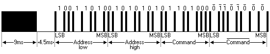
Protocol
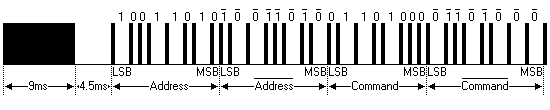
The picture above shows a typical pulse train of the NEC protocol. With this protocol the LSB is transmitted first. In this case Address \(59 and Command \)16 is transmitted. A message is started by a 9ms AGC burst, which was used to set the gain of the earlier IR receivers. This AGC burst is then followed by a 4.5ms space, which is then followed by the Address and Command. Address and Command are transmitted twice. The second time all bits are inverted and can be used for verification of the received message. The total transmission time is constant because every bit is repeated with its inverted length. If you’re not interested in this reliability you can ignore the inverted values, or you can expand the Address and Command to 16 bits each!
Keep in mind that one extra 560µs burst has to follow at the end of the message in order to be able to determine the value of the last bit.
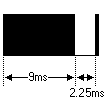
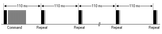
A command is transmitted only once, even when the key on the remote control remains pressed. Every 110ms a repeat code is transmitted for as long as the key remains down. This repeat code is simply a 9ms AGC pulse followed by a 2.25ms space and a 560µs burst.
Extended NEC protocol
The NEC protocol is so widely used that soon all possible addresses were used up. By sacrificing the address redundancy the address range was extended from 256 possible values to approximately 65000 different values. This way the address range was extended from 8 bits to 16 bits without changing any other property of the protocol.
By extending the address range this way the total message time is no longer constant. It now depends on the total number of 1’s and 0’s in the message. If you want to keep the total message time constant you’ll have to make sure the number 1’s in the address field is 8 (it automatically means that the number of 0’s is also 8). This will reduce the maximum number of different addresses to just about 13000.
The command redundancy is still preserved. Therefore each address can still handle 256 different commands.
Keep in mind that 256 address values of the extended protocol are invalid because they are in fact normal NEC protocol addresses. Whenever the low byte is the exact inverse of the high byte it is not a valid extended address.
3. Test Code:
The IR receiver on the PCB board is controlled by GPIO19 of the ESP32 board.
#include <IRremote.hpp>

#define IR_RECEIVE_PIN   19   // Defines infrared receiver module pins
IRrecv irrecv(IR_RECEIVE_PIN);     // Creates a class object that receives the class
decode_results results;     // Create a decoded result class object

void setup() {
  Serial.begin(115200);       // Example Initialize the serial port and set the baud rate to 115200
  IrReceiver.begin(IR_RECEIVE_PIN, ENABLE_LED_FEEDBACK);  // Start receiver
}

void loop() {
  if (IrReceiver.decode()) {
      Serial.println(IrReceiver.decodedIRData.decodedRawData, HEX);  // Print raw data
      //IrReceiver.printIRResultShort(&Serial); // Print the complete received data in one line
      //IrReceiver.printIRSendUsage(&Serial);  // Print the statement needed to send this data
      IrReceiver.resume(); // Enable receiving the next value
  }
  delay(100);
}
4. Test Result:
Upload the code to the ESP32 board(if the code can’t be uploaded, you can clickand press Boot, as shown below
Power up with a USB cable, open the serial monitor and set baud rate to 115200. Press a key on the IR remote control, you will view a code on the serial monitor. If 0 shows up, just ignore it.
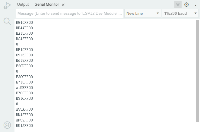
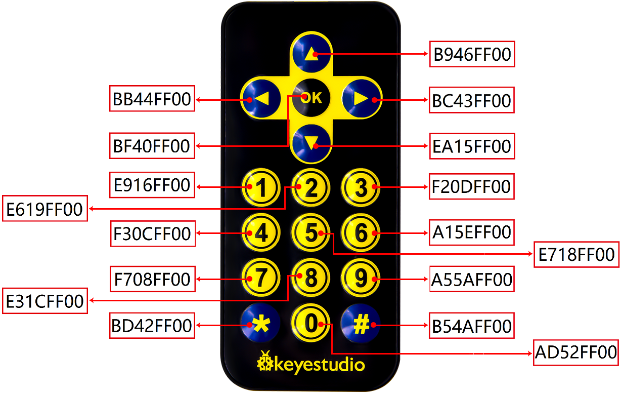
Code of each key
Project 14: IR Remote Control Car
1. Description:
In the above experiment, we have learned about the knowledge of the 8*8 dot matrix display, the motor driver and speed regulation, the infrared receiver and the infrared remote control. In this experiment, we will use the infrared remote control and the infrared receiver to control the car.
2. Working Principle:
Keys |
Keys Code |
Functions |
|---|---|---|
|
B946FF00 |
Go forward |
|
EA15FF00 |
Go back |
|
BB44FF00 |
Turn left |
|
BC43FF00 |
Turn right |
|
BF40FF00 |
stop |


3. Flow Chart:

4. Test Code:
/*
Project 14:IR Remote Control Car
*/
#include <IRremote.hpp>
#include <ESP32Servo.h>

//IR reception
const uint16_t RECV_PIN = 19;  //IR reception pins
IRrecv irrecv(RECV_PIN); //initialize pins of IR receiver
decode_results results; //Create a decoded result class object

//motor
#define left_ctrl  33  //define direction control pins of the left motor as gpio33
#define left_pwm  26   //define PWM control pins of the left motor as gpio26.
#define right_ctrl  32 //define direction control pins of the right motor as gpio32.
#define right_pwm  25  //define PWM control pins of the right motor as gpio25

//servo
const int servoPin = 4;//set the pin of the servo to gpio4.
Servo myservo;  // create servo object to control a servo

void setup() {
  Serial.begin(115200);//open the serial port and set baud rate to 115200
  pinMode(left_ctrl,OUTPUT); //set control pins of the left motor to OUTPUT
  ledcAttach(left_pwm, 1200, 8); //Set the frequency of left_pwm pin to 1200, PWM resolution to 8 that duty cycle is 256.
  pinMode(right_ctrl,OUTPUT);//set direction control pins of the right motor to OUTPUT..
  ledcAttach(right_pwm, 1200, 8); //Set the frequency of right_pwm pin to 1200, PWM resolution to 8 that duty cycle is 256.

  // In case the interrupt driver crashes on setup, give a clue
  // to the user what's going on.

  IrReceiver.begin(RECV_PIN, ENABLE_LED_FEEDBACK); // Start receiver

  myservo.setPeriodHertz(50);           // standard 50 hz servo
  myservo.attach(servoPin, 500, 2500);  // attaches the servo on servoPin to the servo object.
  myservo.write(90);  // the initial angle of the servo is set to 90° .
  delay(300);
}

void loop() {
  if (IrReceiver.decode()) {
    Serial.println(IrReceiver.decodedIRData.decodedRawData, HEX);  // Print raw data
    handleControl(IrReceiver.decodedIRData.decodedRawData); //Handle commands from remote control
    IrReceiver.resume();  // Receive the next value
  }
}

void handleControl(unsigned long irr_val){
  switch(irr_val)
  {
    case 0xB946FF00 :
      car_front();
      break;
    case 0xEA15FF00 :
      car_back();
      break;
    case 0xBB44FF00 :
      car_left();
      break;
    case 0xBC43FF00 :
      car_right();
      break;
    case 0xBF40FF00 :
      car_Stop();
      break;
  }
}

void car_front()//define the state of going forward
{
  digitalWrite(left_ctrl,LOW); //set direction control pins of the left motor to LOW.
  ledcWrite(left_pwm, 150); //the left motor outputs PWM 150
  digitalWrite(right_ctrl,LOW); //set control pins of the right motor to LOW.
  ledcWrite(right_pwm, 150); //the right motor outputs PWM 150
}
void car_back()//define the state of going back
{
  digitalWrite(left_ctrl,HIGH); //set direction control pins of the left motor to HIGH..
  ledcWrite(left_pwm, 150); //the left motor outputs PWM 150
  digitalWrite(right_ctrl,HIGH); //set control pins of the right motor to HIGH..
  ledcWrite(right_pwm, 150); //the right motor outputs PWM 150
}
void car_left()//define the state of turning left
{
  digitalWrite(left_ctrl,HIGH); //set direction control pins of the left motor to HIGH..
  ledcWrite(left_pwm, 150); //the left motor outputs PWM 150
  digitalWrite(right_ctrl,LOW); //set control pins of the right motor to LOW.
  ledcWrite(right_pwm, 150); //the right motor outputs PWM 150
}
void car_right()//define the state of turning right
{
  digitalWrite(left_ctrl,LOW); //set direction control pins of the left motor to LOW.
  ledcWrite(left_pwm, 150); //the left motor outputs PWM 150
  digitalWrite(right_ctrl,HIGH); //set control pins of the right motor to HIGH..
  ledcWrite(right_pwm, 150); //the right motor outputs PWM 150
}
void car_Stop()//define the state of stopping
{
  digitalWrite(left_ctrl,LOW);//set direction control pins of the left motor to LOW.
  ledcWrite(left_pwm, 0); //the left motor outputs PWM 0
  digitalWrite(right_ctrl,LOW);//set control pins of the right motor to LOW.
  ledcWrite(right_pwm, 0); //the right motor outputs PWM 0
}
5. Test Result:
Upload the code to the ESP32 board(if the code can’t be uploaded, you can click and press Boot, as shown below
Place batteries in the car, turn the power switch to ON end and power up. Turn the power switch to the ON end, power up and press a key of the IR remote control. Then the car will make the corresponding movement.
Project 15: WIFI Station Mode
1. Description:
One of the most useful features of the ESP32 is that it can not only act as a Web server, but also to create its own network for other devices to connect to and access web pages. ESP32 can run in three modes: Station (STA) mode, Soft Access Point (AP) mode, and Station+AP mode.
Station mode: Actively connect to the router as a WiFi device, also known as WiFi Client
AP mode: As an Access Point for other WiFi devices to connect to, i.e., WiFi hotspots
Station+AP mode: While the ESP32 connects to the router, it is also a hotspot for other WiFi devices to connect to.
All WiFi programming projects must be configured with WiFi running mode before using, otherwise the WiFi cannot be used. In this project, we are going to learn the ESP32 WiFi Station Mode.
2. Components
|
|
|---|---|
USB Cable x1 |
ESP32*1 |

3. Wiring Diagram
Plug the ESP32 to the USB port of your PC.
4. Component Knowledge:
Station mode:
When setting Station mode, the ESP32 is taken as a WiFi client. It can connect to the router network and communicate with other devices on the router via a WiFi connection. As shown in the figure below, the PC and the router have been connected. If the ESP32 wants to communicate with the PC, the PC and the router need to be connected.

5. Test Code:
⚠️ATTENTION: Before uploading code, please replace the WiFi name(REPLACE_WITH_YOUR_SSID) in the code and the passwords(REPLACE_WITH_YOUR_PASSWORD) into yours.
/*
  Project 15: WiFi Station Mode
  Description : Connect to your router using ESP32
*/
#include <WiFi.h>

const char *ssid_Router     = "REPLACE_WITH_YOUR_SSID"; //Enter the router name
const char *password_Router = "REPLACE_WITH_YOUR_PASSWORD"; //Enter the router password

void setup(){
  Serial.begin(115200);
  delay(2000);
  Serial.println("Setup start");
  WiFi.begin(ssid_Router, password_Router);
  Serial.println(String("Connecting to ")+ssid_Router);
  while (WiFi.status() != WL_CONNECTED){
    delay(500);
    Serial.print(".");
  }
  Serial.println("\nConnected, IP address: ");
  Serial.println(WiFi.localIP());
  Serial.println("Setup End");
}

void loop() {
}
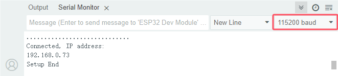
6. Test Result
Upload the code to the ESP32 board(if the code can’t be uploaded, you can click and press Boot, as shown below
Open the serial monitor and set baud rate to 115200, turn the power switch to ON end and power up.
When the ESP32 successfully connects to ssid_WiFi, the serial monitor will print out the IP address that the WiFi assigned to the ESP32. Then the serial monitor window will appear as follows:
Project 16:WIFI AP Mode
1. Component Knowledge:
AP Mode:
When setting AP mode, a hotspot network will be created, waiting for other WiFi devices to connect. As shown below;
take the ESP32 as the hotspot. If a phone or PC needs to communicate with the ESP32, it must be connected to the ESP32’s hotspot. Communication is only possible after a connection is established via the ESP32.

2. Test Code:
⚠️ATTENTION: The AP name, AP password, local_IP, gateway and IP address do not need to be modified, and can be directly used.
/*
  Project 16: WiFi AP Mode
  Description : Set ESP32 to open an access point
*/
#include <WiFi.h>

const char *ssid_AP     = "ESP32_Wifi"; //Enter the AP name
const char *password_AP = "12345678"; //Enter the AP password

IPAddress local_IP(192,168,1,126);//Set the IP address of ESP32 itself
IPAddress gateway(192,168,1,10);   //Set the gateway of ESP32 itself
IPAddress subnet(255,255,255,0);  //Set the subnet mask for ESP32 itself

void setup(){
  Serial.begin(115200);
  delay(2000);
  Serial.println("Setting soft-AP configuration ... ");
  WiFi.disconnect();
  WiFi.mode(WIFI_AP);
  Serial.println(WiFi.softAPConfig(local_IP, gateway, subnet) ? "Ready" : "Failed!");
  Serial.println("Setting soft-AP ... ");
  boolean result = WiFi.softAP(ssid_AP, password_AP);
  if(result){
    Serial.println("Ready");
    Serial.println(String("Soft-AP IP address = ") + WiFi.softAPIP().toString());
    Serial.println(String("MAC address = ") + WiFi.softAPmacAddress().c_str());
  }else{
    Serial.println("Failed!");
  }
  Serial.println("Setup End");
}

void loop() {
}
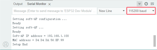
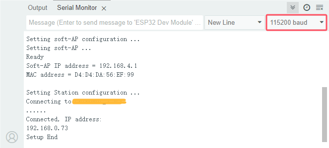
3. Test Result
Upload the code to the ESP32 board(if the code can’t be uploaded, you can click and press Boot, as shown below
Open the serial monitor and set baud rate to 115200 and power up. The serial monitor will display as follows;
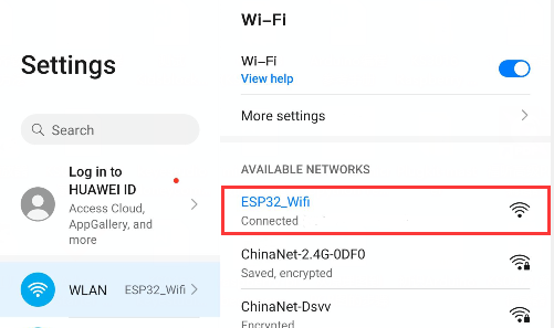
When observing the printed information of the serial monitor, turn on the WiFi scanning function of the mobile phone, and you can see the ssid_AP which is called “ESP32_Wifi” in the code. You can enter the password “12345678” to connect it, or you can modify its AP name and password by modifying the program code.
Project 17:WIFI AP+Station Mode
1. Component Knowledge:
AP+Station mode
In addition to the AP mode and the Station mode, AP+Station can be used at the same time. Turn on the Station mode of the ESP32, connect it to the router network, and it can communicate with the Internet through the router. Then turn on the AP mode to create a hotspot network. Other WiFi devices can be connected to the router network or the hotspot network to communicate with the ESP32.
2. Test Code:
⚠️ATTENTION: Before uploading code, please replace the WiFi name(REPLACE_WITH_YOUR_SSID) in the code and the passwords(REPLACE_WITH_YOUR_PASSWORD) into yours.
But, the AP name, AP password, local_IP, gateway and IP address do not need to be modified, and can be directly used.
/*
  Project 17:  WiFi AP+Station Mode
  Description : ESP32 connects to the user's router, turning on an access point
*/
#include <WiFi.h>

const char *ssid_Router     =  "REPLACE_WITH_YOUR_SSID";  //Enter the router name
const char *password_Router =  "REPLACE_WITH_YOUR_PASSWORD";  //Enter the router password
const char *ssid_AP         =  "ESP32_Wifi"; //Enter the AP name
const char *password_AP     =  "12345678";  //Enter the AP password

void setup(){
  Serial.begin(115200);
  Serial.println("Setting soft-AP configuration ... ");
  WiFi.disconnect();
  WiFi.mode(WIFI_AP);
  Serial.println("Setting soft-AP ... ");
  boolean result = WiFi.softAP(ssid_AP, password_AP);
  if(result){
    Serial.println("Ready");
    Serial.println(String("Soft-AP IP address = ") + WiFi.softAPIP().toString());
    Serial.println(String("MAC address = ") + WiFi.softAPmacAddress().c_str());
  }else{
    Serial.println("Failed!");
  }

  Serial.println("\nSetting Station configuration ... ");
  WiFi.begin(ssid_Router, password_Router);
  Serial.println(String("Connecting to ")+ ssid_Router);
  while (WiFi.status() != WL_CONNECTED){
    delay(500);
    Serial.print(".");
  }
  Serial.println("\nConnected, IP address: ");
  Serial.println(WiFi.localIP());
  Serial.println("Setup End");
}

void loop() {
}
3. Test Result
Upload the code to the ESP32 board(if the code can’t be uploaded, you can click and press Boot, as shown below
Open the serial monitor and set baud rate to 115200. Then the monitor will show as follows;
If the serial monitor does not display the following information, you can press the reset button on the ESP32 board.

Observe the information printed on the serial display, turn on your cellphone and search WiFi, then you can see the ssid_AP on the ESP32.
Project 18:Read WiFi APP Button String
1. Description:
In the previous experiments, we have learned about the three modes of ESP32: WIFI Station mode, WIFI AP mode and WIFI AP+Station mode. Then in this chapter, we will use the WIFI Station mode of ESP32 to control a multi-function car via app
In this experiment, we first use the WIFI Station mode of ESP32 to read the characters via app.
2. Components
|
|
|
USB cable x1 |
ESP32*1 |
Cellphone/iPad*1 |


3. Install APP
Android system:
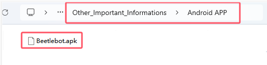
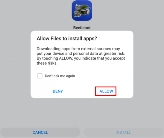
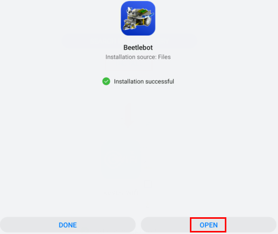
Transfer the file Beetlebot.apk to your cellphone or IPAD, click it to install, and click“ALLOW”→“INSTALL”→“OPEN”.


IOS system
Open App Store

Search Beetlebot,click“ ”to download Beetlebot.
The installation instructions are similar with Android system.
4. Test Code:
⚠️ATTENTION: Before uploading code, please replace the WiFi name(REPLACE_WITH_YOUR_SSID) in the code and the passwords(REPLACE_WITH_YOUR_PASSWORD) into yours.
// generated by KidsBlock
#include <Arduino.h>
#include <WiFi.h>
#include <ESPmDNS.h>
#include <WiFiClient.h>

String item = "0";
/*REPLACE WITH YOUR NETWORK CREDENTIALS(Put your SSID & Password)*/
const char* ssid = "REPLACE_WITH_YOUR_SSID"; //Enter SSID here
const char* password = "REPLACE_WITH_YOUR_PASSWORD";  //Enter Password here
WiFiServer server(80);

void setup() {
  Serial.begin(115200);
  WiFi.begin(ssid, password);
  while (WiFi.status() != WL_CONNECTED) {
    delay(500);
    Serial.print(".");
  }
  Serial.println("");
  Serial.print("Connected to ");
  Serial.println(ssid);
  Serial.print("IP address: ");
  Serial.println(WiFi.localIP());
  server.begin();
  Serial.println("TCP server started");
  MDNS.addService("http", "tcp", 80);
}

void loop() {
  WiFiClient client = server.available();
  if (!client) {
      return;
  }
  while(client.connected() && !client.available()){
      delay(1);
  }
  String req = client.readStringUntil('\r');
  int addr_start = req.indexOf(' ');
  int addr_end = req.indexOf(' ', addr_start + 1);
  if (addr_start == -1 || addr_end == -1) {
      Serial.print("Invalid request: ");
      Serial.println(req);
      return;
  }
  req = req.substring(addr_start + 1, addr_end);
  item=req;
  Serial.println(item);
  String s;
  if (req == "/")
  {
      IPAddress ip = WiFi.localIP();
      String ipStr = String(ip[0]) + '.' + String(ip[1]) + '.' + String(ip[2]) + '.' + String(ip[3]);
      s = "HTTP/1.1 200 OK\r\nContent-Type: text/html\r\n\r\n<!DOCTYPE HTML>\r\n<html>Hello from ESP32 at ";
      s += ipStr;
      s += "</html>\r\n\r\n";
      Serial.println("Sending 200");
      client.println(s);
  }
  //client.print(s);
  client.stop();
}
5. Test Result
Upload the code to the ESP32 board(if the code can’t be uploaded, you can click and press Boot, as shown below
Place batteries in the car, turn the power switch to ON end and power up.
Open the serial monitor and set baud rate to 115200; then the monitor will print detected WiFi IP address, open app to enter the detected Wifi IP address in the text box, as shown below;
For example, the following IP address is 192.168.1.137. Then click button  to connect wifi.
If the IP address 192.168.1.137 is shown in the test box, which means wifi is connected with app.
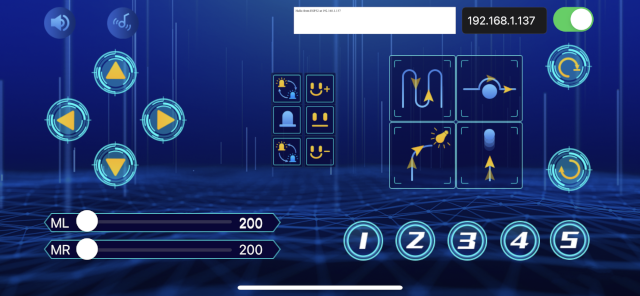
Click each key on app, then the monitor will receive corresponding characters
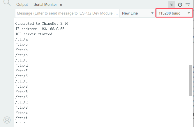
If the monitor doesn’t display anything, press reset button to reboot
Project 19:WiFi Control 8*8 Dot Matrix Display
1. Description:
In this experiment, we will use the WIFI Station mode to control the 8*8 dot matrix display on the car through APP and WIFI.
2. Install APP
⚠️Special note: If you have downloaded and installed the APP, this step is skipped; If not, please refer to the installation instructions of link: Project 18:Read WiFi APP Button String .
3. Test Code
⚠️ATTENTION: Before uploading code, please replace the WiFi name(REPLACE_WITH_YOUR_SSID) in the code and the passwords(REPLACE_WITH_YOUR_PASSWORD) into yours.
// generated by KidsBlock
#include <Arduino.h>
#include <WiFi.h>
#include <ESPmDNS.h>
#include <WiFiClient.h>
#include <HT16K33_Lib_For_ESP32.h>

String item = "0";
/*REPLACE WITH YOUR NETWORK CREDENTIALS(Put your SSID & Password)*/
const char* ssid = "REPLACE_WITH_YOUR_SSID"; //Enter SSID here
const char* password = "REPLACE_WITH_YOUR_PASSWORD";  //Enter Password here
WiFiServer server(80);

//matrix
//pin GPIO21,GPIO22
#define SDA 21
#define SCL 22
ESP32_HT16K33 matrix = ESP32_HT16K33();
//Array, used to store the data of the pattern,
//can be calculated yourself or retrieved from the touch tool
byte front[8]={0x12,0x24,0x48,0x90,0x90,0x48,0x24,0x12};
byte back[8]={0x48,0x24,0x12,0x09,0x09,0x12,0x24,0x48};
byte left[8]={0x18,0x24,0x42,0x99,0x24,0x42,0x81,0x00};
byte right[8]={0x00,0x81,0x42,0x24,0x99,0x42,0x24,0x18};
byte stop1[8]={0x00,0x00,0x00,0xfd,0xfd,0x00,0x00,0x00};

void setup() {
  Serial.begin(115200);
  WiFi.begin(ssid, password);
  while (WiFi.status() != WL_CONNECTED) {
    delay(500);
    Serial.print(".");
  }
  Serial.println("");
  Serial.print("Connected to ");
  Serial.println(ssid);
  Serial.print("IP address: ");
  Serial.println(WiFi.localIP());
  server.begin();
  Serial.println("TCP server started");
  MDNS.addService("http", "tcp", 80);

  matrix.init(0x70, SDA, SCL);// matrix init
  matrix.clear(); //clear
  matrix.setBrightness(10);
}

void loop() {
  WiFiClient client = server.available();
  if (!client) {
      return;
  }
  while(client.connected() && !client.available()){
      delay(1);
  }
  String req = client.readStringUntil('\r');
  int addr_start = req.indexOf(' ');
  int addr_end = req.indexOf(' ', addr_start + 1);
  if (addr_start == -1 || addr_end == -1) {
      Serial.print("Invalid request: ");
      Serial.println(req);
      return;
  }
  req = req.substring(addr_start + 1, addr_end);
  item=req;
  Serial.println(item);
  String s;
  if (req == "/")
  {
      IPAddress ip = WiFi.localIP();
      String ipStr = String(ip[0]) + '.' + String(ip[1]) + '.' + String(ip[2]) + '.' + String(ip[3]);
      s = "HTTP/1.1 200 OK\r\nContent-Type: text/html\r\n\r\n<!DOCTYPE HTML>\r\n<html>Hello from ESP32 at ";
      s += ipStr;
      s += "</html>\r\n\r\n";
      Serial.println("Sending 200");
      client.println(s);
  }
  else if(req == "/btn/i")
  {
    Serial.write('i');
    client.println(F("i"));
    matrix.showLedMatrix(front,0,0);//Show forward pattern
    matrix.show();//show
  }
  else if(req == "/btn/j")
  {
    Serial.write('j');
    client.println(F("j"));
    matrix.showLedMatrix(stop1,0,0);
    matrix.show();
  }
  else if(req == "/btn/k")
  {
    Serial.write('k');
    client.println(F("k"));
    matrix.showLedMatrix(back,0,0);
    matrix.show();
  }
  //client.print(s);
  client.stop();
}
4. Test Result:
Upload the code to the ESP32 board(if the code can’t be uploaded, you can click and press Boot, as shown below
Click  , the 8*8 display will show the forward pattern, click
  , the stop pattern will be shown the stop pattern and click
  , the display module will show the backward pattern.
If the monitor doesn’t display anything, press reset button to reboot
Project 20:WiFi Control Multi-purpose Car
1. Description:
In this project we will demonstrate how to control the car through APP and WIFI.
2. Install APP
⚠️Special note: If you have downloaded and installed the APP, this step is skipped; If not, please refer to the APP installation instructions of link: Project 18:Read WiFi APP Button String .
3. Test Code
⚠️ATTENTION: Before uploading code, please replace the WiFi name(REPLACE_WITH_YOUR_SSID) in the code and the passwords(REPLACE_WITH_YOUR_PASSWORD) into yours.
#include <WiFi.h>
#include <ESPmDNS.h>
#include <WiFiClient.h>
#include <Adafruit_NeoPixel.h>
Adafruit_NeoPixel ledStrip(4, 14, NEO_GRB + NEO_KHZ800);
#include <ESP32Servo.h>

#include <HT16K33_Lib_For_ESP32.h>
//define pins as GPIO21 and GPIO22
#define SDA 21
#define SCL 22
ESP32_HT16K33 matrix = ESP32_HT16K33();
//Array, used to store pattern data, which can be calculated by yourself or obtained from the touch tool
uint8_t matrix_smile[8]={0x60, 0x80, 0x64, 0x02, 0x02, 0x64, 0x80, 0x60};
uint8_t matrix_front[8]={0x12, 0x24, 0x48, 0x90, 0x90, 0x48, 0x24, 0x12};
uint8_t matrix_back[8]={0x48, 0x24, 0x12, 0x09, 0x09, 0x12, 0x24, 0x48};
uint8_t matrix_left[8]={0x18, 0x24, 0x42, 0x99, 0x24, 0x42, 0x81, 0x00};
uint8_t matrix_right[8]={0x00, 0x81, 0x42, 0x24, 0x99, 0x42, 0x24, 0x18};
uint8_t matrix_stop[8]={0x00, 0x00, 0x00, 0xfd, 0xfd, 0x00, 0x00, 0x00};
uint8_t matrix_tsundere[8]={0x40, 0x40, 0x48, 0x10, 0x48, 0x44, 0x40, 0x00};
uint8_t matrix_squinting[8]={0x44, 0x28, 0x12, 0x02, 0x02, 0x12, 0x28, 0x44};
uint8_t matrix_despise1[8]={0x30, 0x10, 0x14, 0x04, 0x34, 0x10, 0x10, 0x00};
uint8_t matrix_speechless[8]={0x40, 0x40, 0x5c, 0x14, 0x5c, 0x40, 0x40, 0x40};
uint8_t matrix_heart[8]={0x30, 0x48, 0x44, 0x22, 0x22, 0x44, 0x48, 0x30};
uint8_t matrix_clear[8]={0x00, 0x00, 0x00, 0x00, 0x00, 0x00, 0x00, 0x00};

const int buzzerPin = 2; //buzzer pin

#define left_ctrl  33  //define direction control pins of the left motor as gpio33
#define left_pwm  26   //define PWM control pins of the left motor as gpio26.
#define right_ctrl  32 //define direction control pins of the right motor as gpio32.
#define right_pwm  25  //define PWM control pins of the right motor as gpio25

/*REPLACE WITH YOUR NETWORK CREDENTIALS(Put your SSID & Password)*/
const char* ssid = "REPLACE_WITH_YOUR_SSID"; //Enter SSID here
const char* password = "REPLACE_WITH_YOUR_PASSWORD"; //Enter Password here

// TCP server at port 80 will respond to HTTP requests
WiFiServer server(80);

//ultrasonic sensor
#define TRIG_PIN 5 // Define the signal input of the ultrasonic sensor as gpio5
#define ECHO_PIN 18 //Define the signal input of the ultrasonic sensor as gpio18
long distance; //define three distance variables

//servo
const int servoPin = 4;//set the pin of the servo to gpio4.
Servo myservo;  // create servo object to control a servo

int flag_neo = 0;
int flag_matrix = 0;
int speed_L = 200;
int speed_R = 200;

void setup(void)
{
    Serial.begin(115200);
    pinMode(left_ctrl,OUTPUT); //set control pins of the left motor to OUTPUT
    ledcAttach(left_pwm, 1200, 8); //Set the frequency of left_pwm pin to 1200, PWM resolution to 8 that duty cycle is 256.
    pinMode(right_ctrl,OUTPUT);//set direction control pins of the right motor to OUTPUT..
    ledcAttach(right_pwm, 1200, 8); //Set the frequency of right_pwm pin to 1200, PWM resolution to 8 that duty cycle is 256.

    pinMode(TRIG_PIN,OUTPUT);//Set TRIG_PIN to OUTPUT.
    pinMode(ECHO_PIN,INPUT);//Set ECHO_PIN to INPUT入.

    myservo.setPeriodHertz(50);           // standard 50 hz servo
    myservo.attach(servoPin, 500, 2500);  // attaches the servo on servoPin to the servo object.
    myservo.write(90);  // the initial angle of the servo is set to 90° .
    delay(300);

    ledcAttach(buzzerPin, 2000, 8); // Set up the PWM pin
    ledcWriteTone(buzzerPin, 0);

    matrix.init(0x70, SDA, SCL);// matrix init
    matrix.clear(); //clear
    matrix.setBrightness(10);

    ledStrip.begin();

    // Connect to WiFi network
    WiFi.begin(ssid, password);
    Serial.println("");

    // Wait for connection
    while (WiFi.status() != WL_CONNECTED) {
        delay(500);
        Serial.print(".");
    }
    Serial.println("");
    Serial.print("Connected to ");
    Serial.println(ssid);
    Serial.print("IP address: ");
    Serial.println(WiFi.localIP());

    // Set up mDNS responder:
    // - first argument is the domain name, in this example
    //   the fully-qualified domain name is "esp32.local"
    // - second argument is the IP address to advertise
    //   we send our IP address on the WiFi network
    if (!MDNS.begin("esp32")) {
        Serial.println("Error setting up MDNS responder!");
        while(1) {
            delay(1000);
        }
    }
    Serial.println("mDNS responder started");

    // Start TCP (HTTP) server
    server.begin();
    Serial.println("TCP server started");

    // Add service to MDNS-SD
    MDNS.addService("http", "tcp", 80);
}

void loop(void)
{
    // Check if a client has connected
    WiFiClient client = server.available();
    if (!client) {
        return;
    }
    //Serial.println("");
    //Serial.println("New client");

    // Wait for data from client to become available
    while(client.connected() && !client.available()){
        delay(1);
    }

    // Read the first line of HTTP request
    String req = client.readStringUntil('\r');
    //Serial.println(req);
    // First line of HTTP request looks like "GET /path HTTP/1.1"
    // Retrieve the "/path" part by finding the spaces
    int addr_start = req.indexOf(' ');
    int addr_end = req.indexOf(' ', addr_start + 1);
    if (addr_start == -1 || addr_end == -1) {
        //Serial.print("Invalid request: ");
        //Serial.println(req);
        return;
    }
    req = req.substring(addr_start + 1, addr_end);
    //Serial.print("Request: ");
    Serial.println(req);
    int len_val = String(req).length();
    String M_req = String(req).substring(0,6);
    //Serial.println(M_req);
    if(M_req == "/btn/u")
    {
      String s_M_req = String(req).substring(6,len_val);
      speed_L = s_M_req.toInt();
      Serial.println(speed_L);
    }
    if(M_req == "/btn/v")
    {
      String s_M_req = String(req).substring(6,len_val);
      speed_R = s_M_req.toInt();
      Serial.println(speed_R);
    }

    String s;
    if (req == "/")
    {
        IPAddress ip = WiFi.localIP();
        String ipStr = String(ip[0]) + '.' + String(ip[1]) + '.' + String(ip[2]) + '.' + String(ip[3]);
        s = "HTTP/1.1 200 OK\r\nContent-Type: text/html\r\n\r\n<!DOCTYPE HTML>\r\n<html>Hello from ESP32 at ";
        s += ipStr;
        s += "</html>\r\n\r\n";
        Serial.println("Sending 200");
        client.println(WiFi.localIP());
    }
    else if(req == "/btn/F")
    {
      digitalWrite(left_ctrl,LOW);
      ledcWrite(left_pwm, speed_L);
      digitalWrite(right_ctrl,LOW);
      ledcWrite(right_pwm, speed_R);
    }
    else if(req == "/btn/B")
    {
      digitalWrite(left_ctrl, HIGH);
      ledcWrite(left_pwm, (255-speed_L));
      digitalWrite(right_ctrl, HIGH);
      ledcWrite(right_pwm, (255-speed_R));
    }
    else if(req == "/btn/L")
    {
      digitalWrite(left_ctrl, HIGH);
      ledcWrite(left_pwm, speed_L);
      digitalWrite(right_ctrl, LOW);
      ledcWrite(right_pwm, (255-speed_R));
    }
    else if(req == "/btn/R")
    {
      digitalWrite(left_ctrl, LOW);
      ledcWrite(left_pwm, (255-speed_L));
      digitalWrite(right_ctrl, HIGH);
      ledcWrite(right_pwm, speed_R);
    }
    else if(req == "/btn/S")
    {
      digitalWrite(left_ctrl, LOW);
      ledcWrite(left_pwm, 0);
      digitalWrite(right_ctrl, LOW);
      ledcWrite(right_pwm, 0);
    }
    else if(req == "/btn/a")
    {
      ledcWriteTone(buzzerPin, 262);
    }
    else if(req == "/btn/b")
    {
      ledcWriteTone(buzzerPin, 0);
    }
    else if(req == "/btn/c")
    {
      ledcWriteTone(buzzerPin, 262);
      delay(200);
      ledcWriteTone(buzzerPin, 294);
      delay(200);
      ledcWriteTone(buzzerPin, 330);
      delay(200);
      ledcWriteTone(buzzerPin, 349);
      delay(200);
      ledcWriteTone(buzzerPin, 392);
      delay(200);
      ledcWriteTone(buzzerPin, 440);
      delay(200);
      ledcWriteTone(buzzerPin, 494);
      delay(200);
    }
    else if(req == "/btn/d")
    {
      ledcWriteTone(buzzerPin, 0);
    }
    else if(req == "/btn/e")
    {
      flag_neo = flag_neo + 1;
      if(flag_neo >= 7)
      {
        flag_neo = 7;
      }
      Serial.println(flag_neo);
      switch(flag_neo)
      {
        case 1: ledStrip.fill(0xff0000, 0, 3);ledStrip.show(); break;
        case 2: ledStrip.fill(0xe6da59, 0, 3);ledStrip.show(); break;
        case 3: ledStrip.fill(0x4cff00, 0, 3);ledStrip.show(); break;
        case 4: ledStrip.fill(0x0077ff, 0, 3);ledStrip.show(); break;
        case 5: ledStrip.fill(0xff10df, 0, 3);ledStrip.show(); break;
        case 6: ledStrip.fill(0x75ffff, 0, 3);ledStrip.show(); break;
        case 7: ledStrip.fill(0xffffff, 0, 3);ledStrip.show(); break;
      }
    }
    else if(req == "/btn/f")
    {
      ledStrip.clear();
      ledStrip.show();
    }
    else if(req == "/btn/g")
    {
      flag_neo = flag_neo - 1;
      Serial.println(flag_neo);
      if(flag_neo <= 1)
      {
        flag_neo = 1;
      }
      switch(flag_neo)
      {
        case 1: ledStrip.fill(0xff0000, 0, 3);ledStrip.show(); break;
        case 2: ledStrip.fill(0xe6da59, 0, 3);ledStrip.show(); break;
        case 3: ledStrip.fill(0x4cff00, 0, 3);ledStrip.show(); break;
        case 4: ledStrip.fill(0x0077ff, 0, 3);ledStrip.show(); break;
        case 5: ledStrip.fill(0xff10df, 0, 3);ledStrip.show(); break;
        case 6: ledStrip.fill(0x75ffff, 0, 3);ledStrip.show(); break;
        case 7: ledStrip.fill(0xffffff, 0, 3);ledStrip.show(); break;
      }
    }
    else if(req == "/btn/z")
    {
      ledStrip.clear();
    }
//    else if(req == "/btn/h")
//    {
//      Serial.write('z');
//      client.println(F("h"));
//    }
    else if(req == "/btn/i")
    {
      flag_matrix = flag_matrix + 1;
      if(flag_matrix >= 10)
      {
        flag_matrix = 10;
      }
      Serial.println(flag_matrix);
      switch(flag_matrix)
      {
        case 1: matrix.showLedMatrix(matrix_smile,0,0);matrix.show(); break;
        case 2: matrix.showLedMatrix(matrix_tsundere,0,0);matrix.show(); break;
        case 3: matrix.showLedMatrix(matrix_squinting,0,0);matrix.show(); break;
        case 4: matrix.showLedMatrix(matrix_despise1,0,0);matrix.show(); break;
        case 5: matrix.showLedMatrix(matrix_speechless,0,0);matrix.show(); break;
        case 6: matrix.showLedMatrix(matrix_heart,0,0);matrix.show(); break;
        case 7: matrix.showLedMatrix(matrix_front,0,0);matrix.show(); break;
        case 8: matrix.showLedMatrix(matrix_back,0,0);matrix.show(); break;
        case 9: matrix.showLedMatrix(matrix_left,0,0);matrix.show(); break;
        case 10: matrix.showLedMatrix(matrix_right,0,0);matrix.show(); break;
      }
    }
    else if(req == "/btn/j")
    {
      matrix.clear();
      matrix.show();//Go forward
    }
    else if(req == "/btn/k")
    {
      flag_matrix = flag_matrix - 1;
      if(flag_matrix <= 1)
      {
        flag_matrix = 1;
      }
      Serial.println(flag_matrix);
      switch(flag_matrix)
      {
        case 1: matrix.showLedMatrix(matrix_smile,0,0);matrix.show(); break;
        case 2: matrix.showLedMatrix(matrix_tsundere,0,0);matrix.show(); break;
        case 3: matrix.showLedMatrix(matrix_squinting,0,0);matrix.show(); break;
        case 4: matrix.showLedMatrix(matrix_despise1,0,0);matrix.show(); break;
        case 5: matrix.showLedMatrix(matrix_speechless,0,0);matrix.show(); break;
        case 6: matrix.showLedMatrix(matrix_heart,0,0);matrix.show(); break;
        case 7: matrix.showLedMatrix(matrix_front,0,0);matrix.show(); break;
        case 8: matrix.showLedMatrix(matrix_back,0,0);matrix.show(); break;
        case 9: matrix.showLedMatrix(matrix_left,0,0);matrix.show(); break;
        case 10: matrix.showLedMatrix(matrix_right,0,0);matrix.show(); break;
      }
    }
    else if(req == "/btn/y")
    {
      Serial.write('y');
      client.println(F("y"));
    }
    else if(req == "/btn/l")
    {
      Serial.write('l');
      client.println(F("l"));
    }
    else if(req == "/btn/m")
    {
      Serial.write('m');
      client.println(F("m"));
    }
    else if(req == "/btn/n")
    {
      Serial.write('n');
      client.println("n");
    }
    else if(req == "/btn/o")
    {
      Serial.write('o');
      client.println(F("o"));
    }
    else if(req == "/btn/p")
    {
      Serial.write('p');
      client.println(F("p"));
    }
    else if(req == "/btn/q")
    {
      Serial.write('q');
      client.println("q");
    }
    else if(req == "/btn/x")
    {
      Serial.write('x');
      client.println(F("x"));
    }
    else if(req == "/btn/1")
    {
      Serial.write('1');
      client.println(F("1"));
    }
    else if(req == "/btn/2")
    {
      Serial.write('2');
      client.println("2");
    }
    else if(req == "/btn/3")
    {
      Serial.write('3');
      client.println(F("3"));
    }
    else if(req == "/btn/4")
    {
      Serial.write('4');
      client.println("4");
    }
    else if(req == "/btn/5")
    {
      Serial.write('5');
      client.println(F("5"));
    }
    else if(req == "/btn/0")
    {
      Serial.write('0');
      client.println("0");
    }
    else
    {
        s = "HTTP/1.1 404 Not Found\r\n\r\n";
        Serial.println("Sending 404");
    }
    //client.print(s);

    //client.stop();
    //Serial.println("Done with client");

}

float checkdistance() {
  digitalWrite(TRIG_PIN, LOW);
  delayMicroseconds(2);
  digitalWrite(TRIG_PIN, HIGH);
  delayMicroseconds(10);
  digitalWrite(TRIG_PIN, LOW);
  float distance = pulseIn(ECHO_PIN, HIGH) / 58.00;
  delay(10);
  return distance;
}
4. Test Result:
Upload the code to the ESP32 board(if the code can’t be uploaded, you can click and press Boot, as shown below
Operate the APP according to the figure below to control the WiFi multi-function car
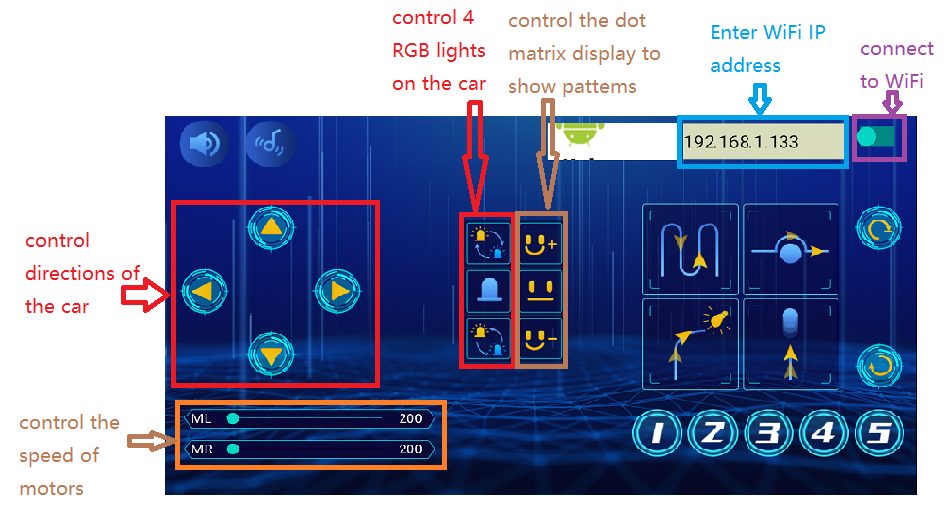
If the monitor doesn’t display anything, press reset button to reboot